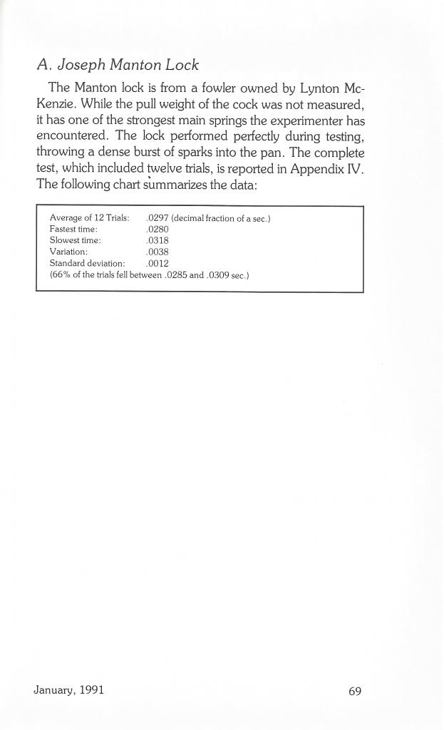
Touch Hole Ignition Timing
Reprinted from February 2000 issue of MuzzleBlasts magazine by Larry Pletcher. I was assisted by Fred Stutzenberger who provided the barrel and any needed machining. The tests conducted here are of straight cylinder vents. This article is a work in progress.
In earlier articles on timing flintlocks, I expressed my belief that touch holes caused some of the slow ignition times experienced occasionally by flintlock shooters. In a pair of articles I hope to shed some light on this idea. This article will report on the testing of touch holes of varying diameters. The touch hole shape for this series of tests is a straight cylinder. These tests are planned as a baseline for future testing. A second article will explore the various touch hole liners available to the flintlock shooter. These liners will have a number of configurations, including cones inside and out, as well as different shapes used in making the cone.
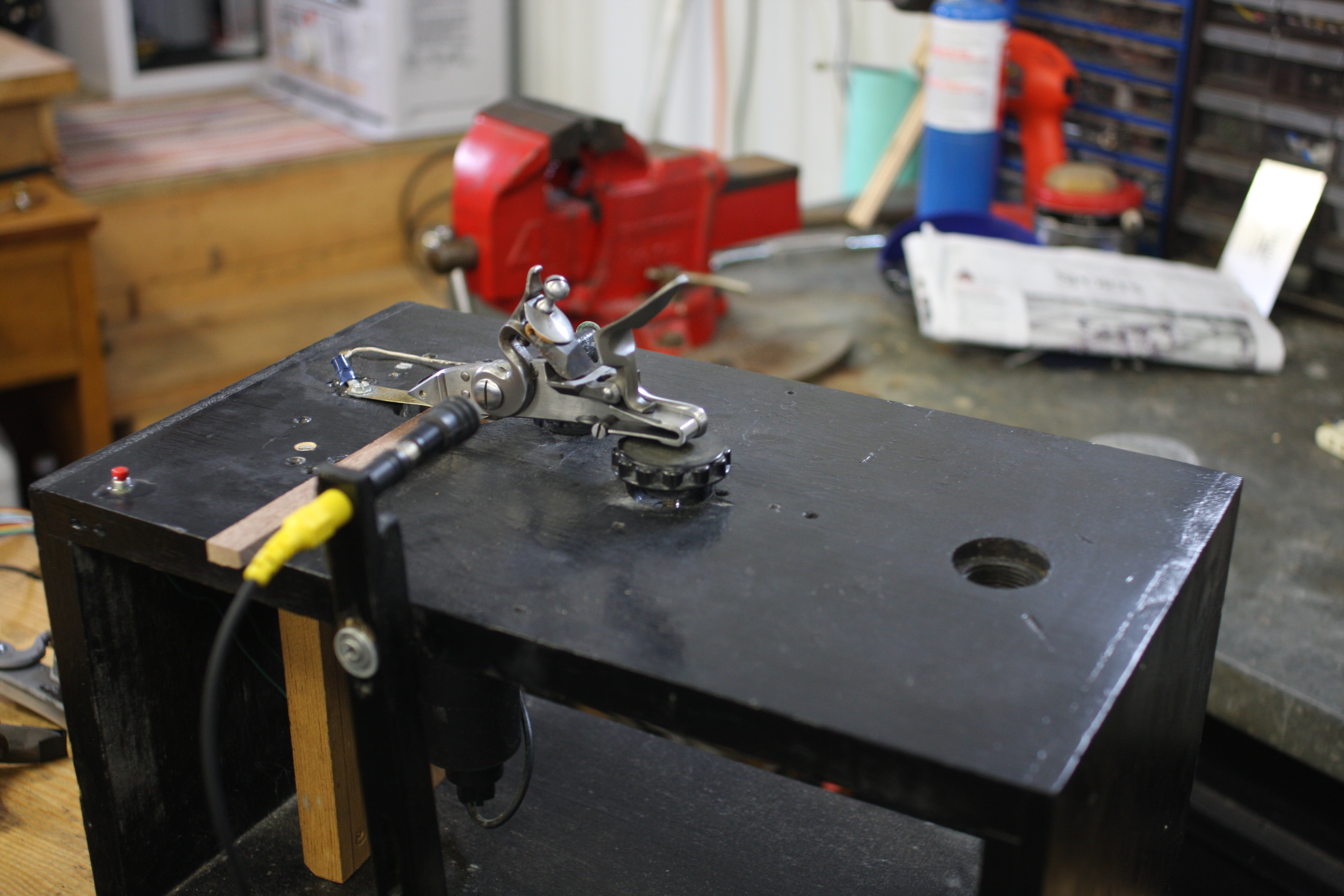
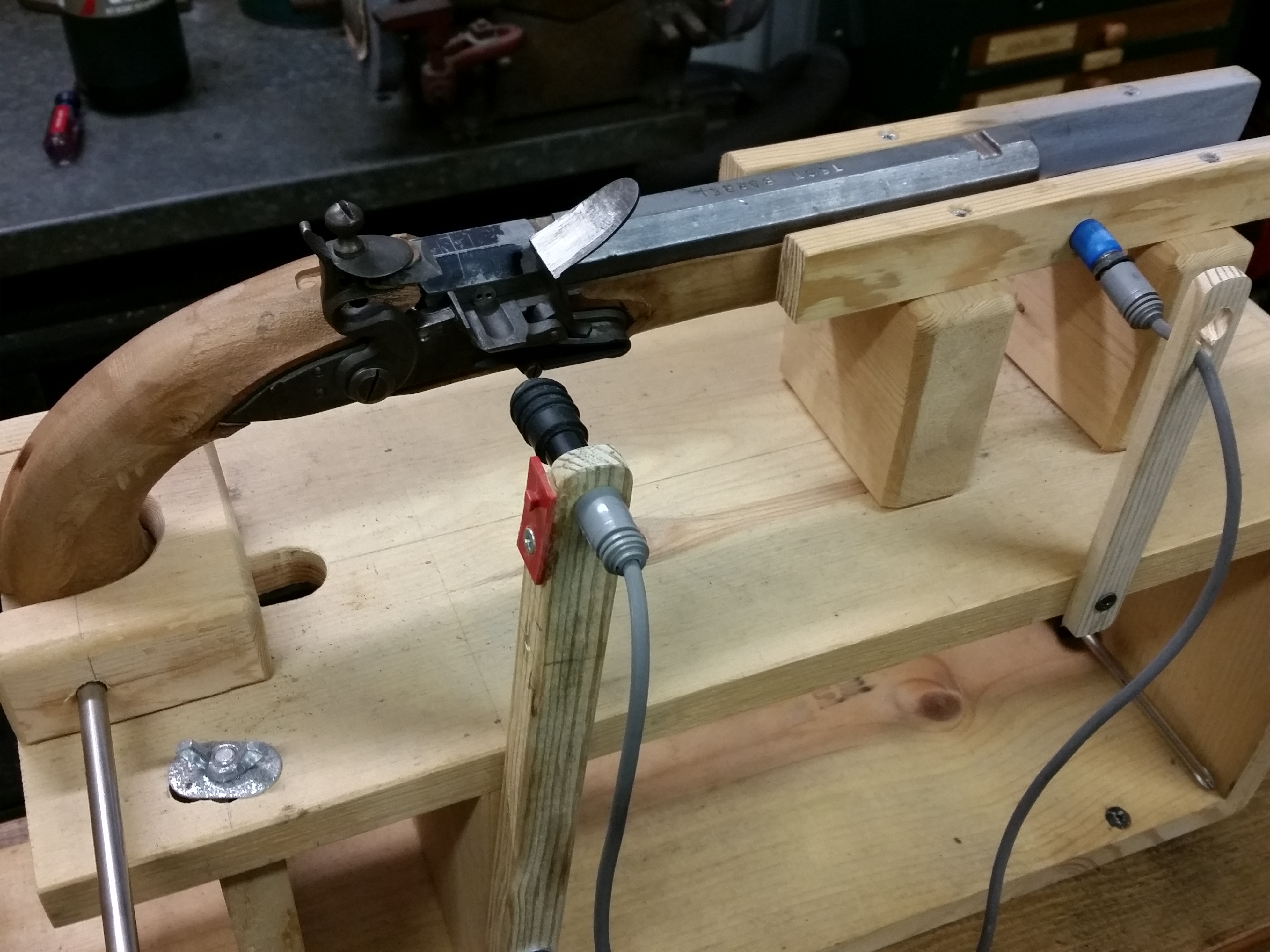
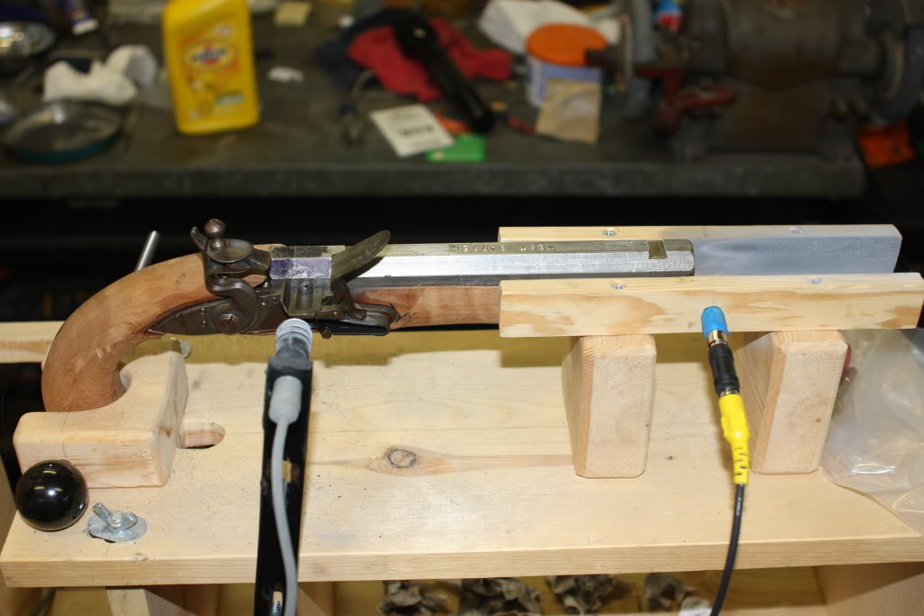
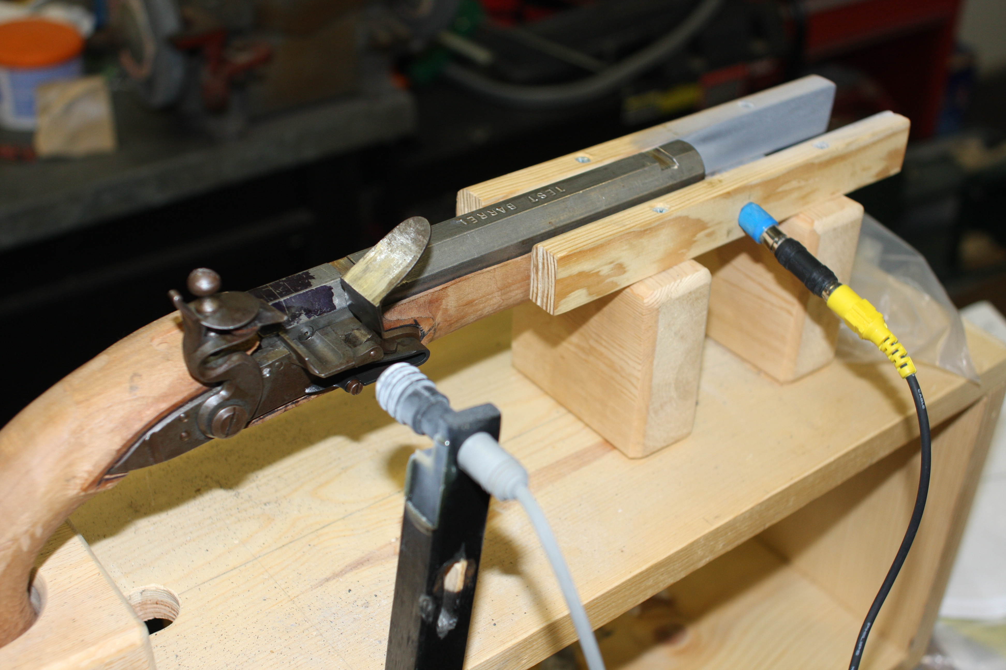
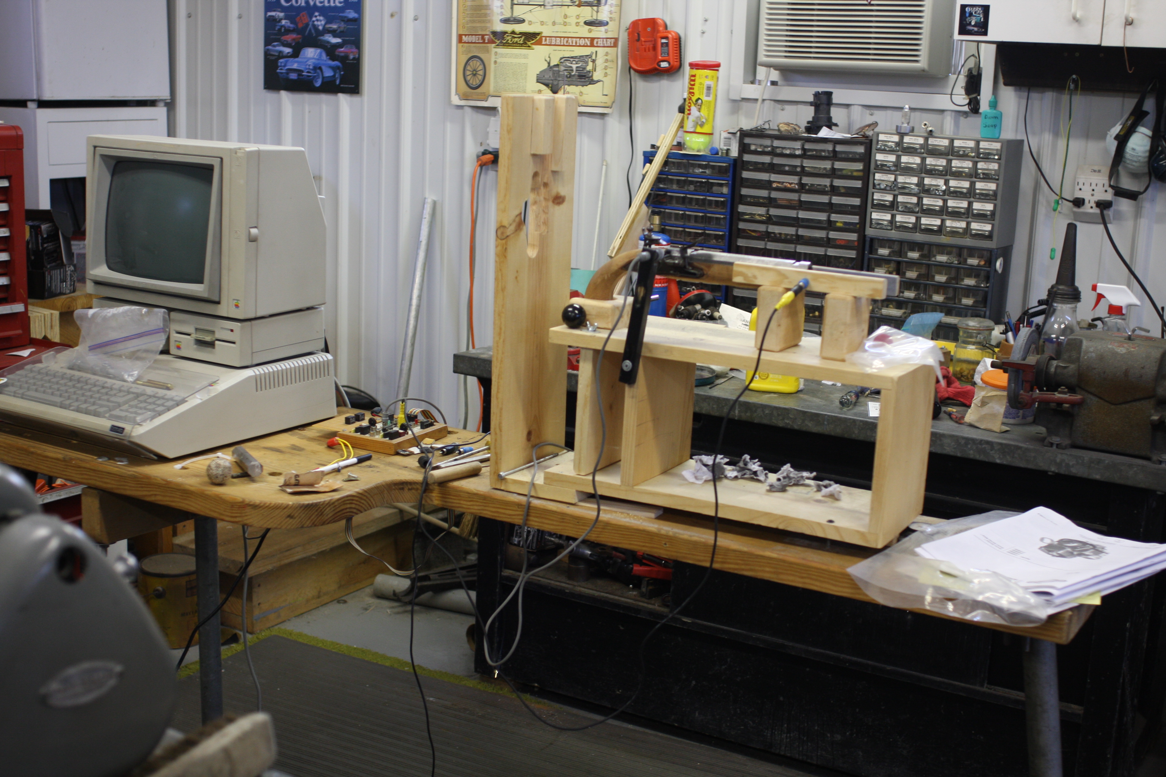
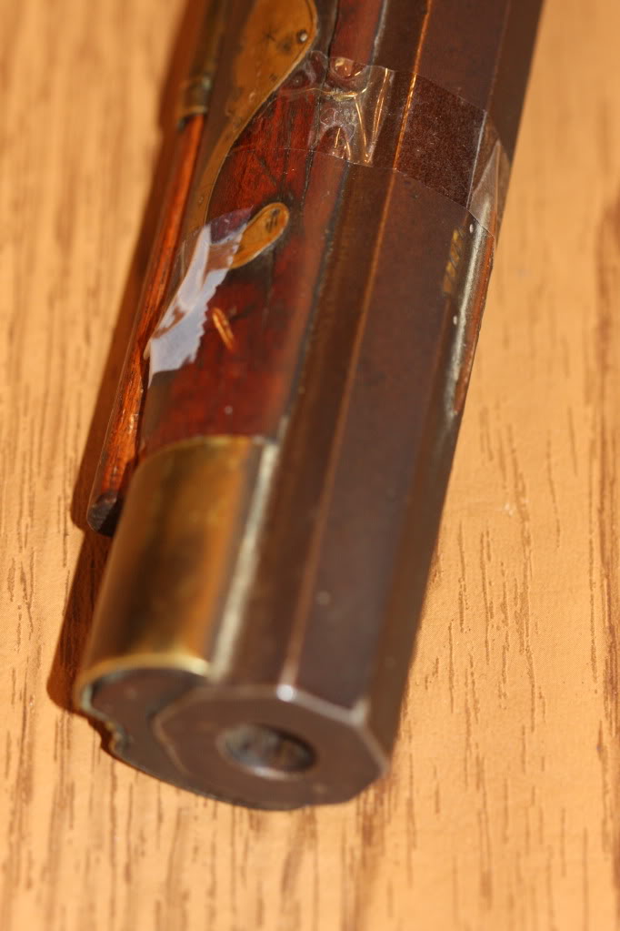
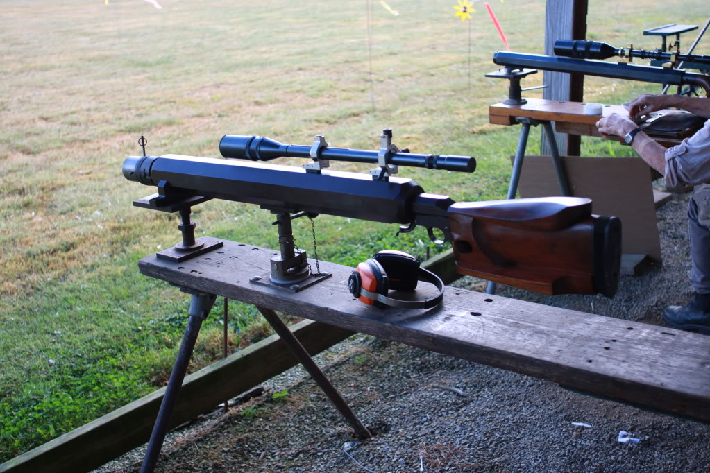
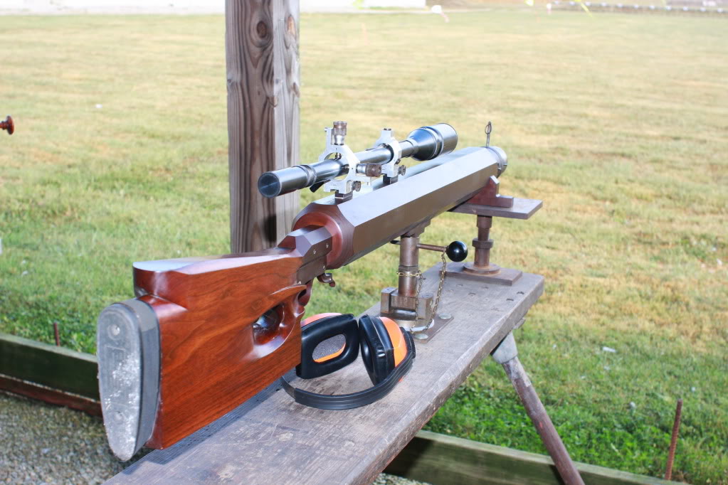
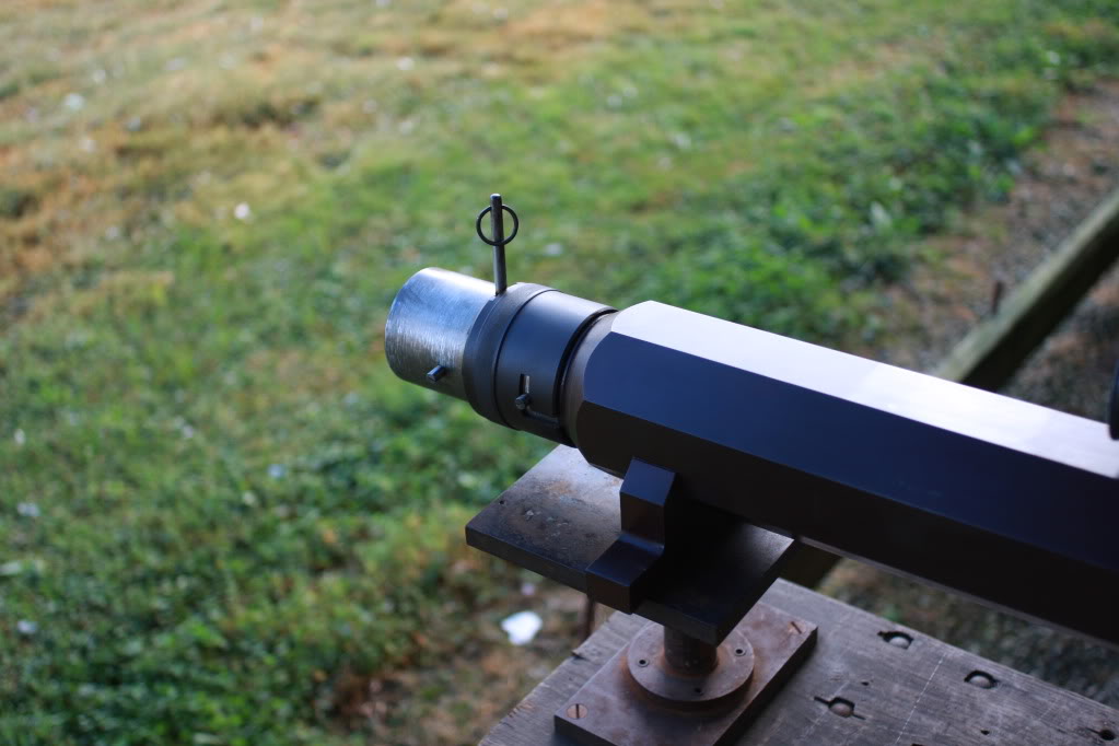
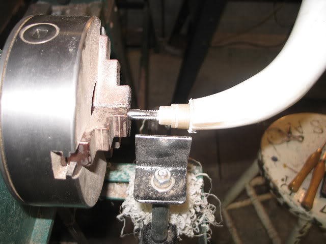
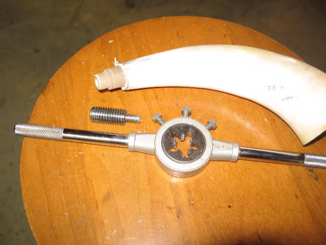
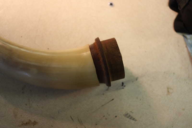
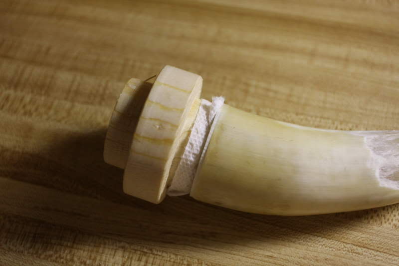
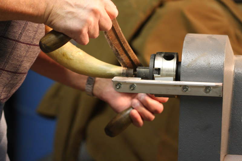
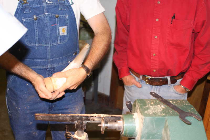
The tests done for this article were conducted on a very short smoothbore barrel in which increasingly larger touch holes were drilled. Another barrel was threaded to this section to conduct smoke away and to provide some space between the photo cells used in the timing process. I am indebted to Fred Stutzenberger for his help in providing the barrel and any machining needed to conduct the tests.
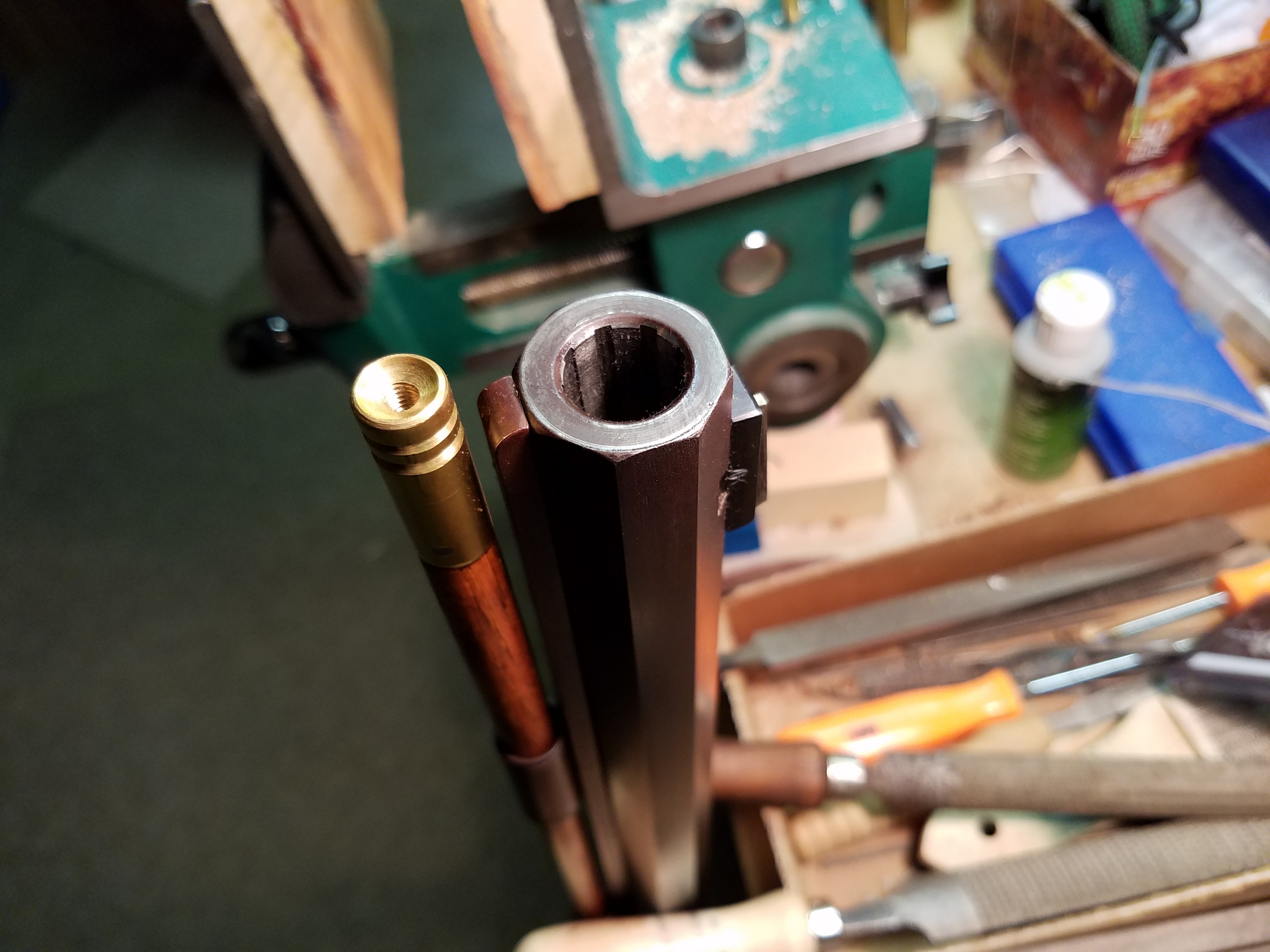
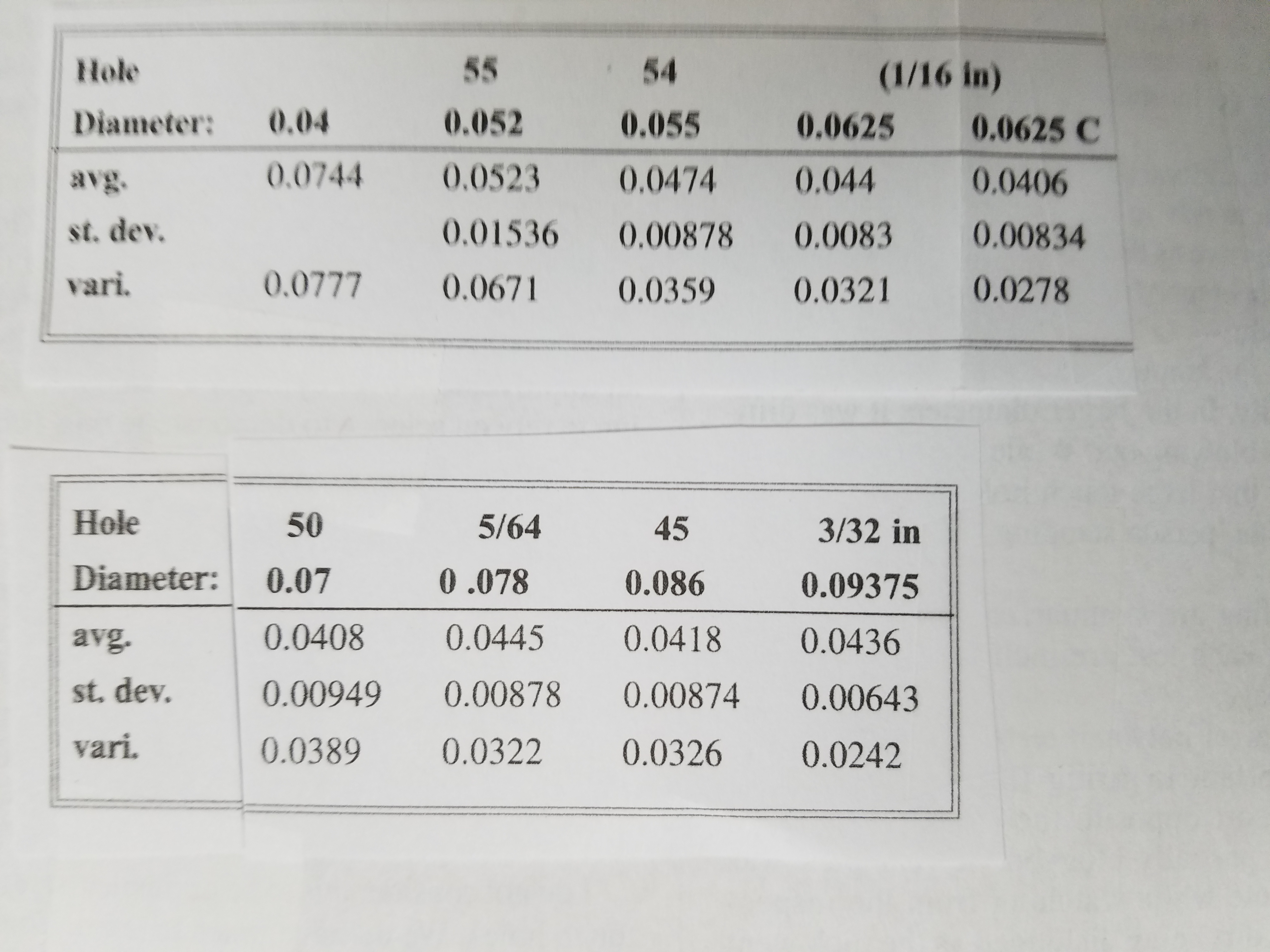
I began with a touch hole which both Fred and I considered too small. We used .040 in. as a starting point. Additional diameters were .052, .055, .0625, .070, .078, .082, .094. These holes correspond to drill numbers 55, 54, 1/16, 50, 5/64, 45, and 42, respectively.
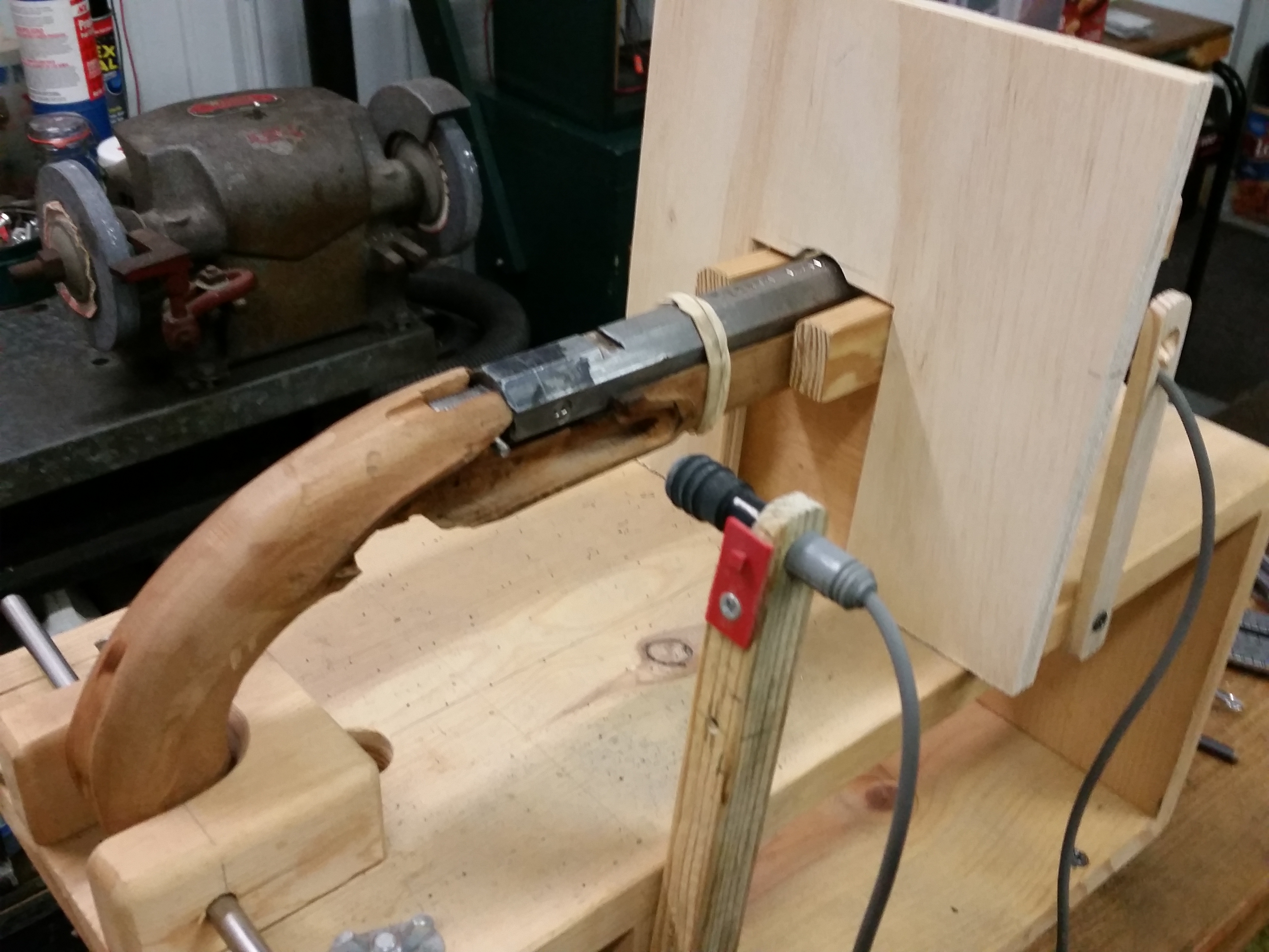
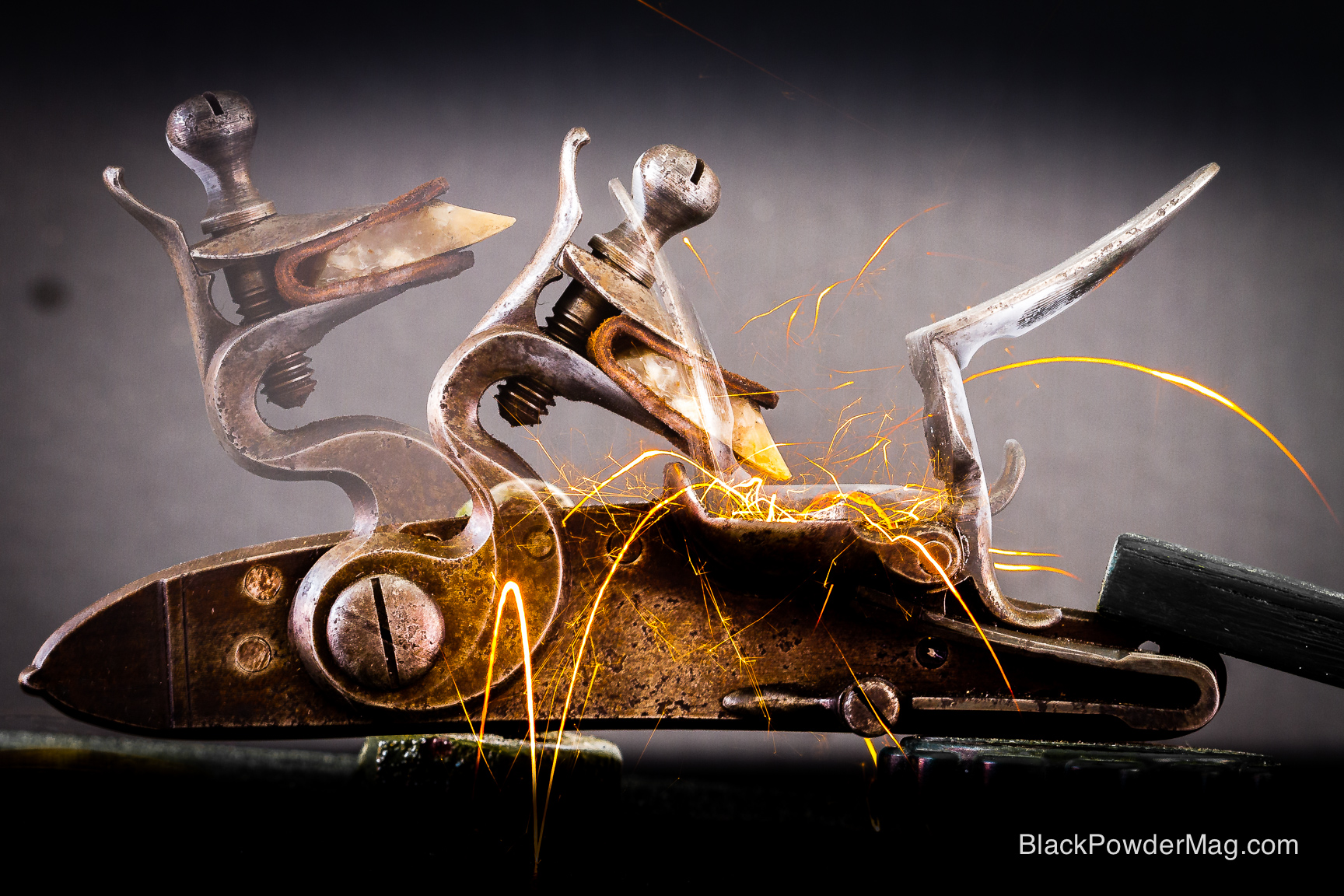
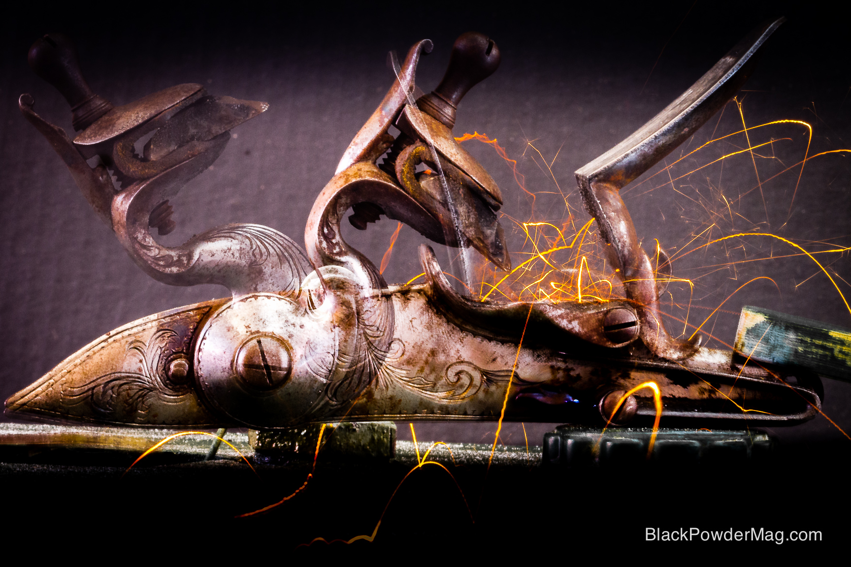
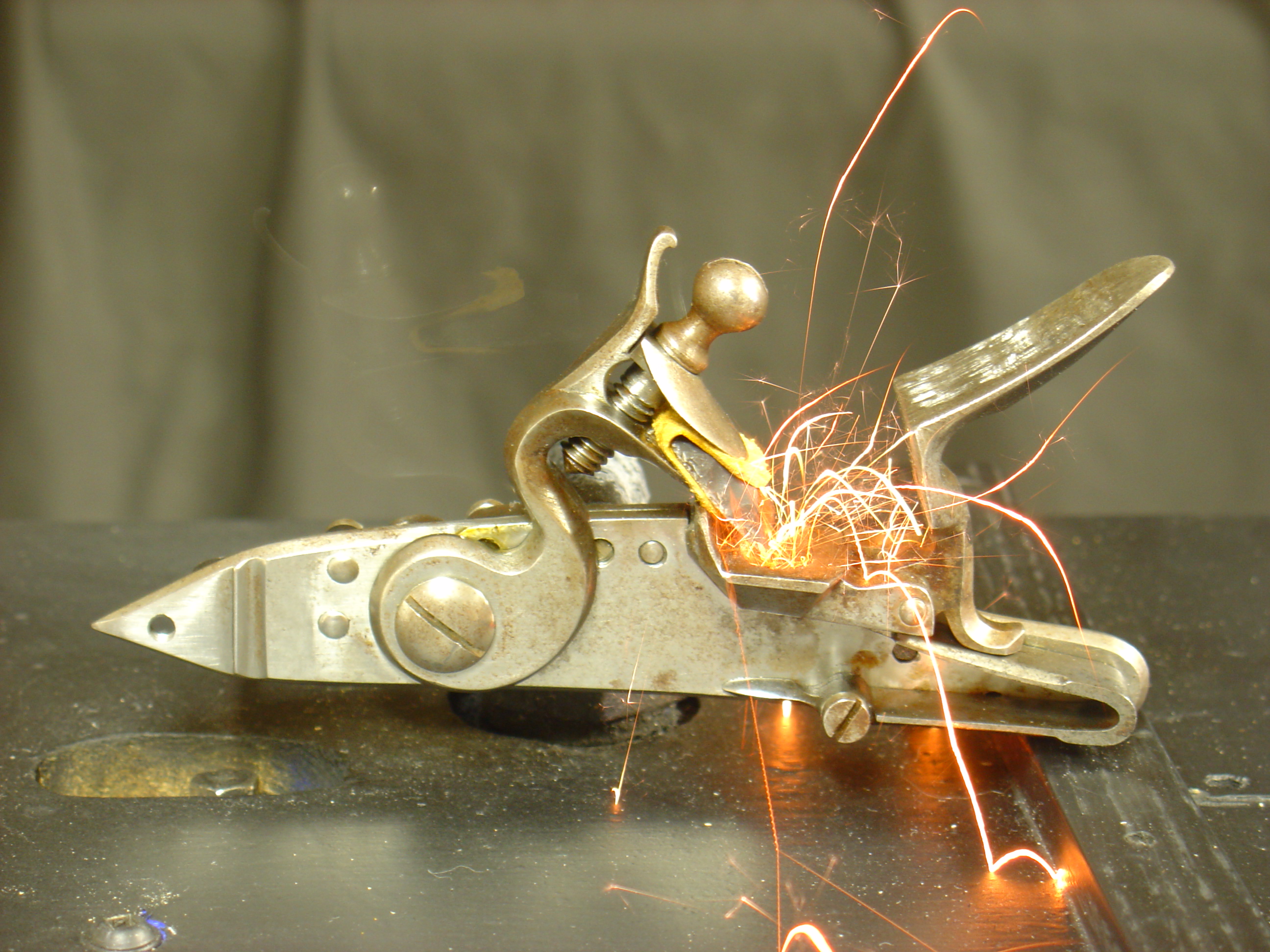
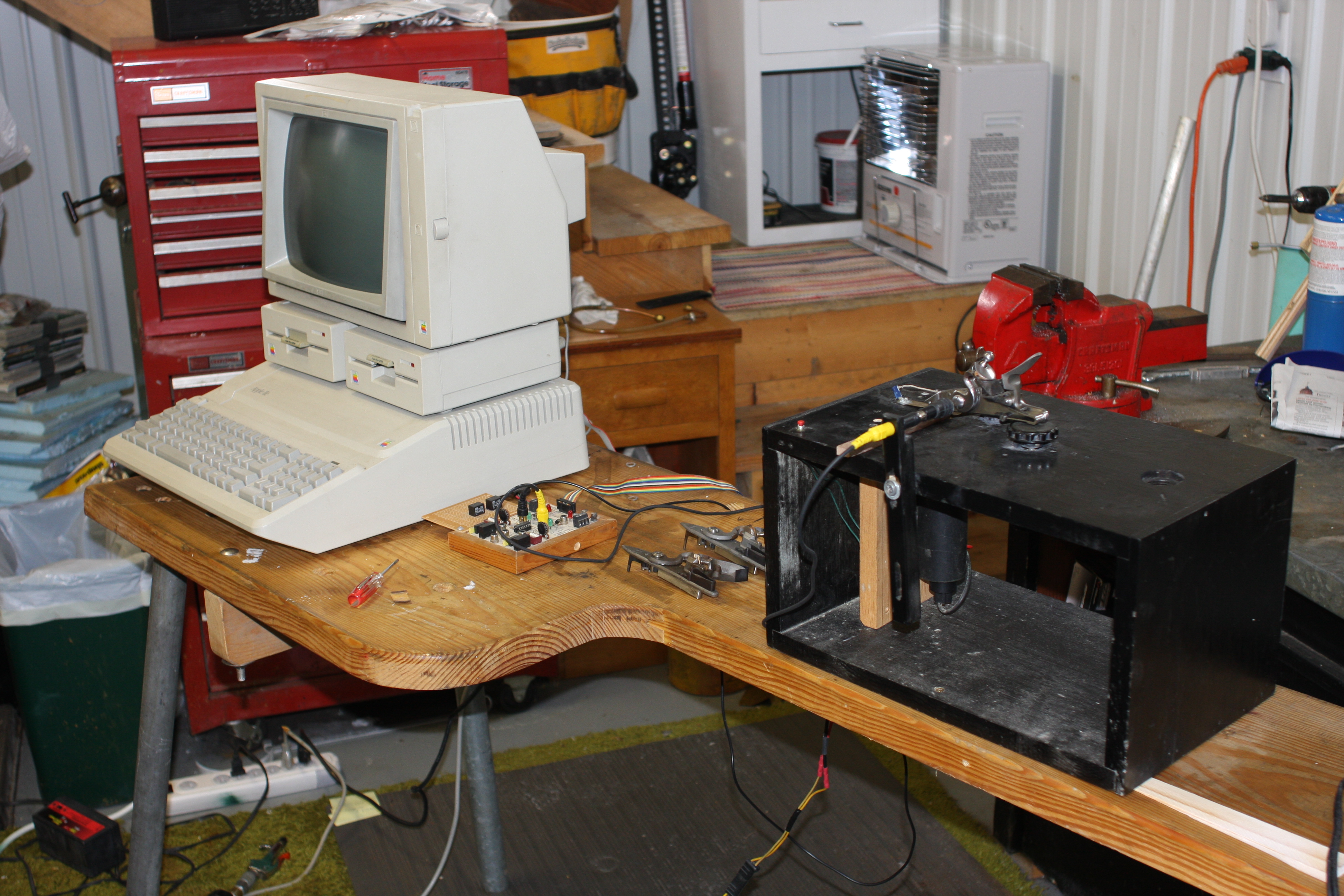
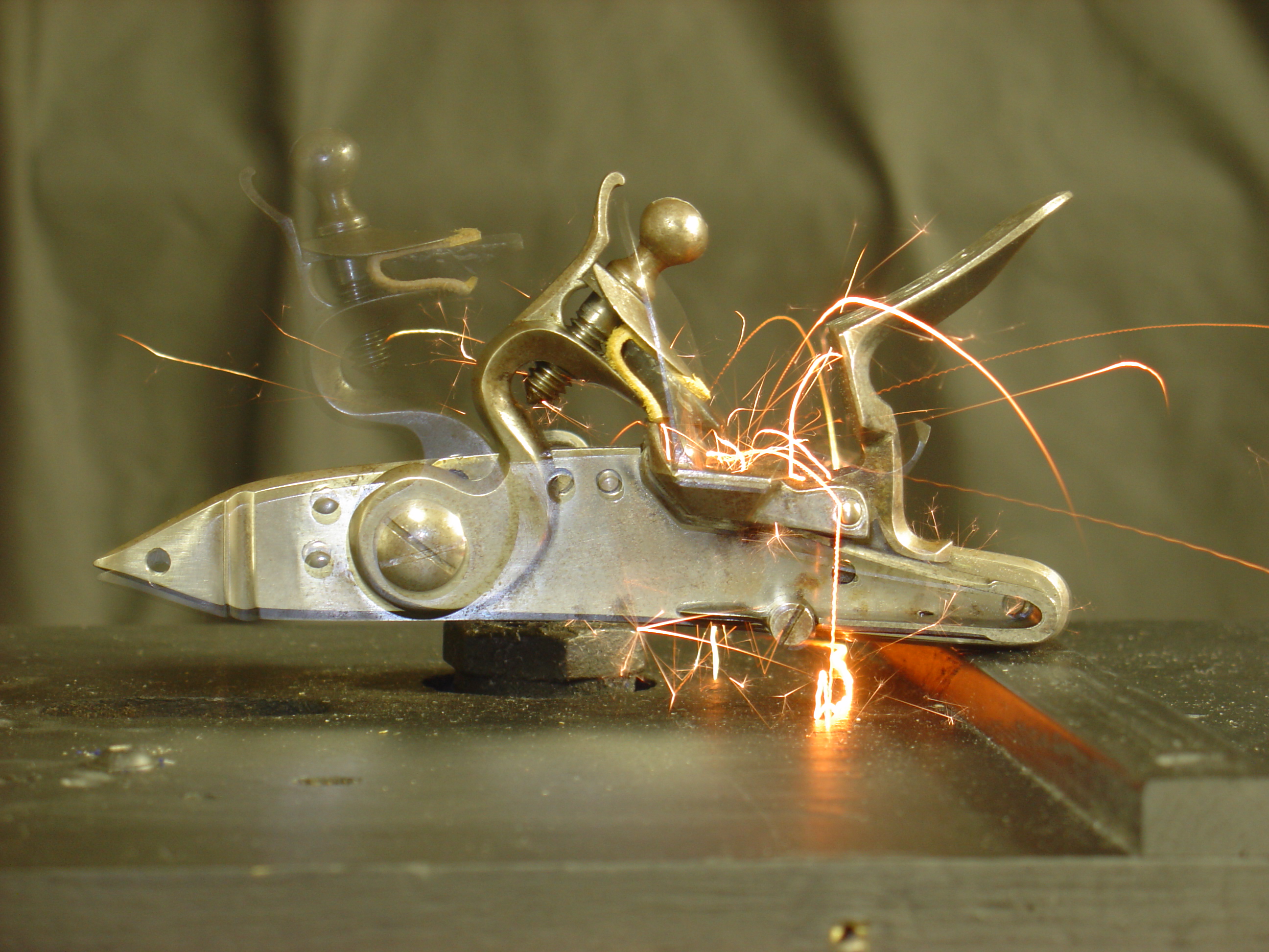
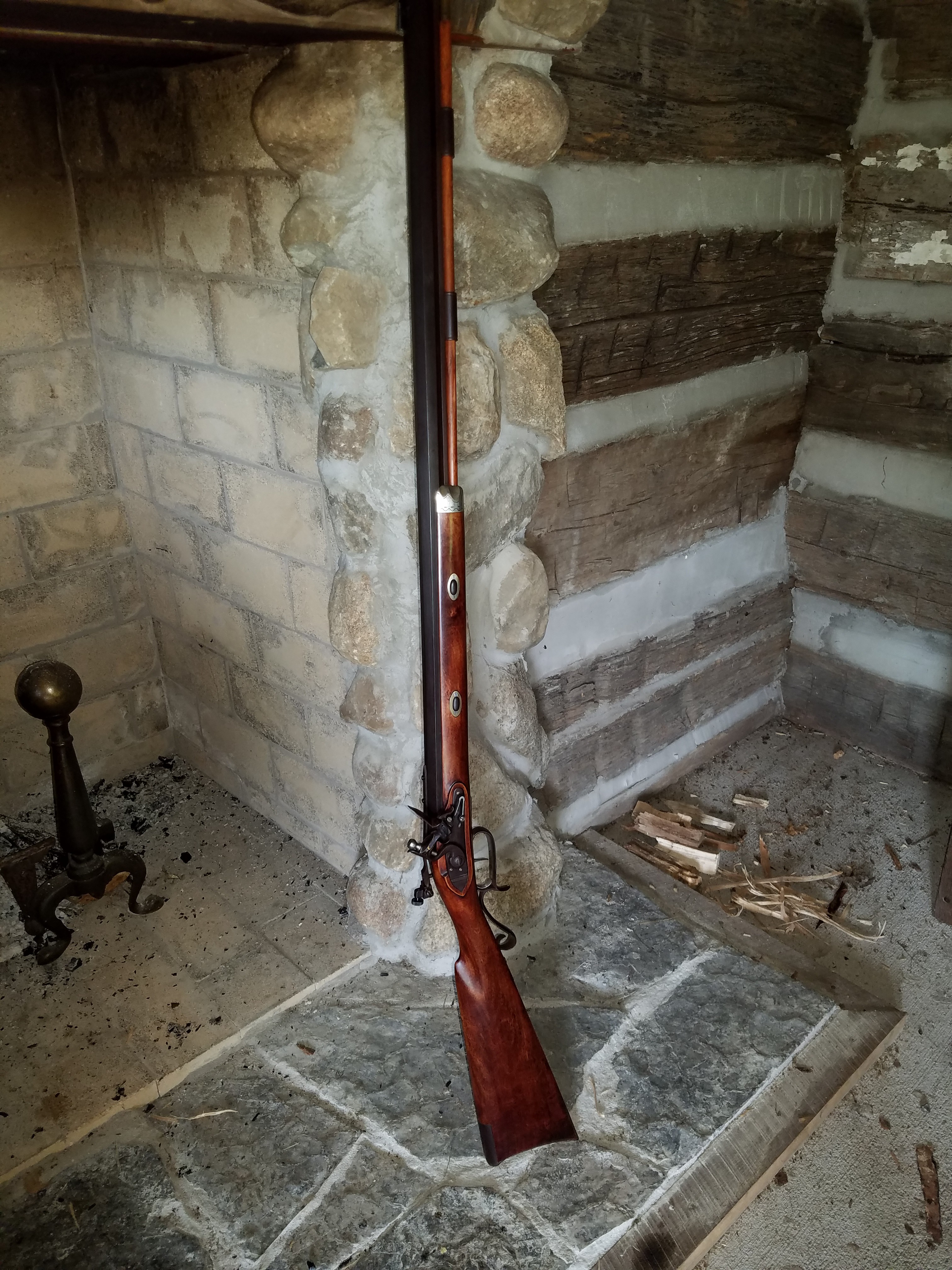
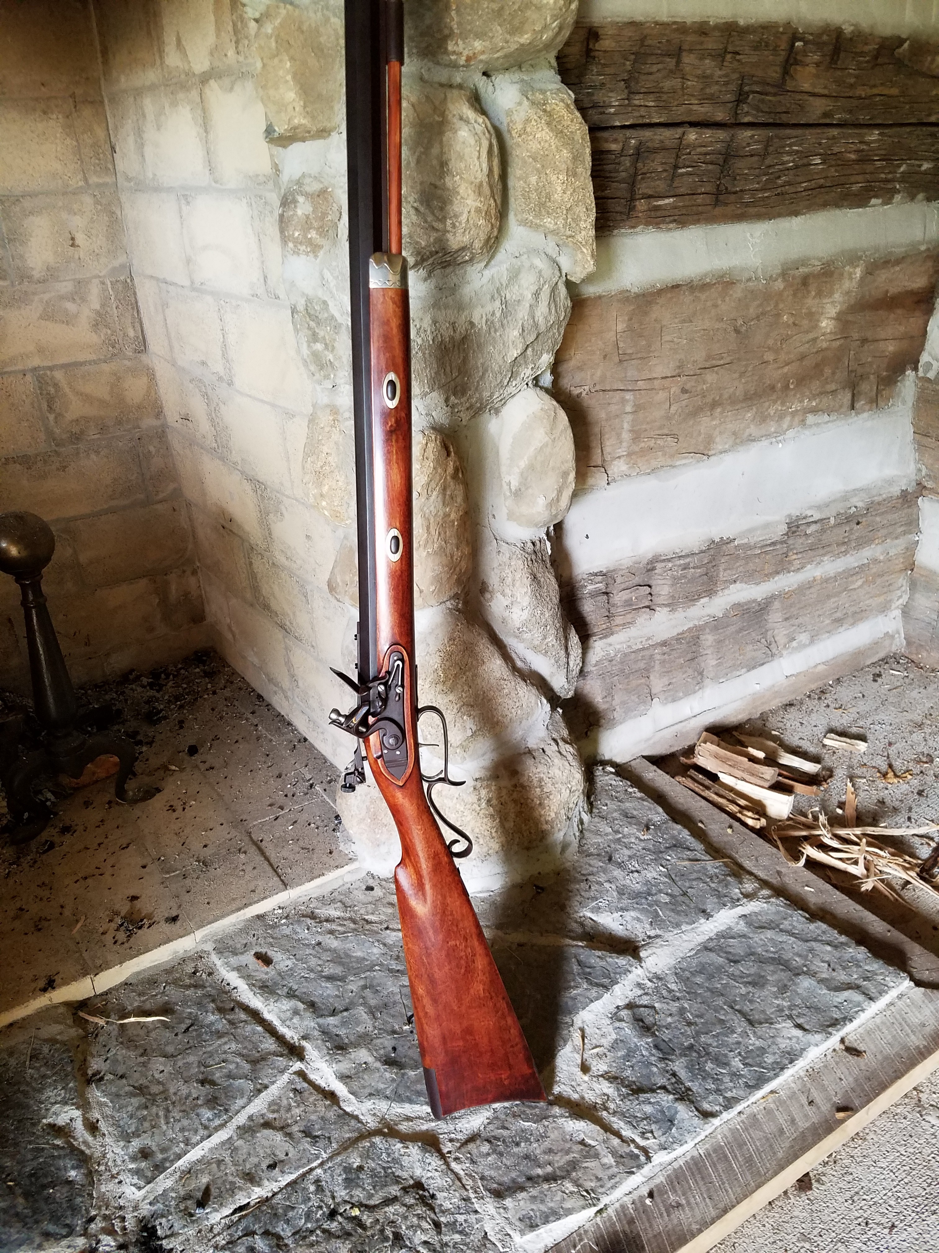
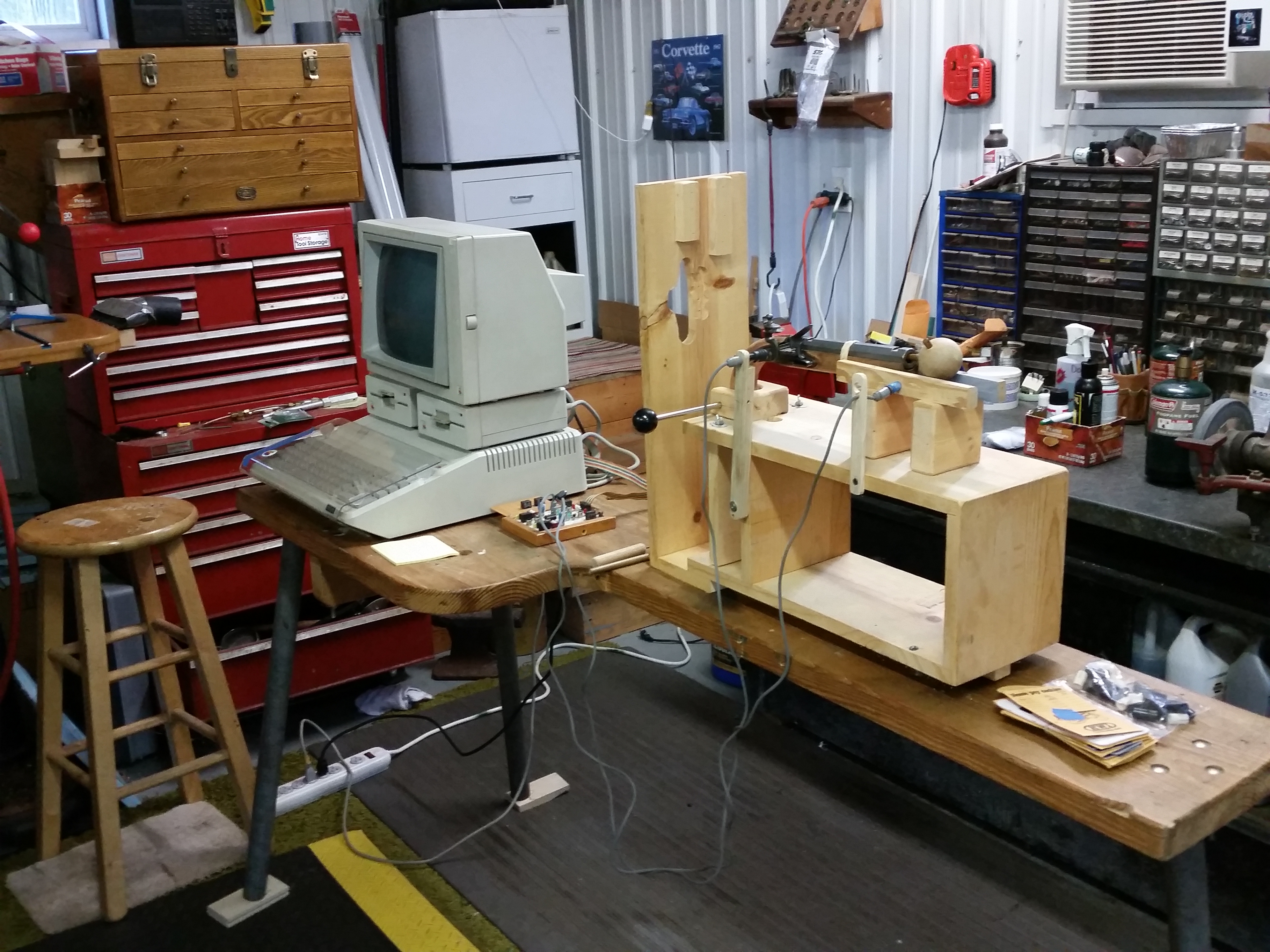
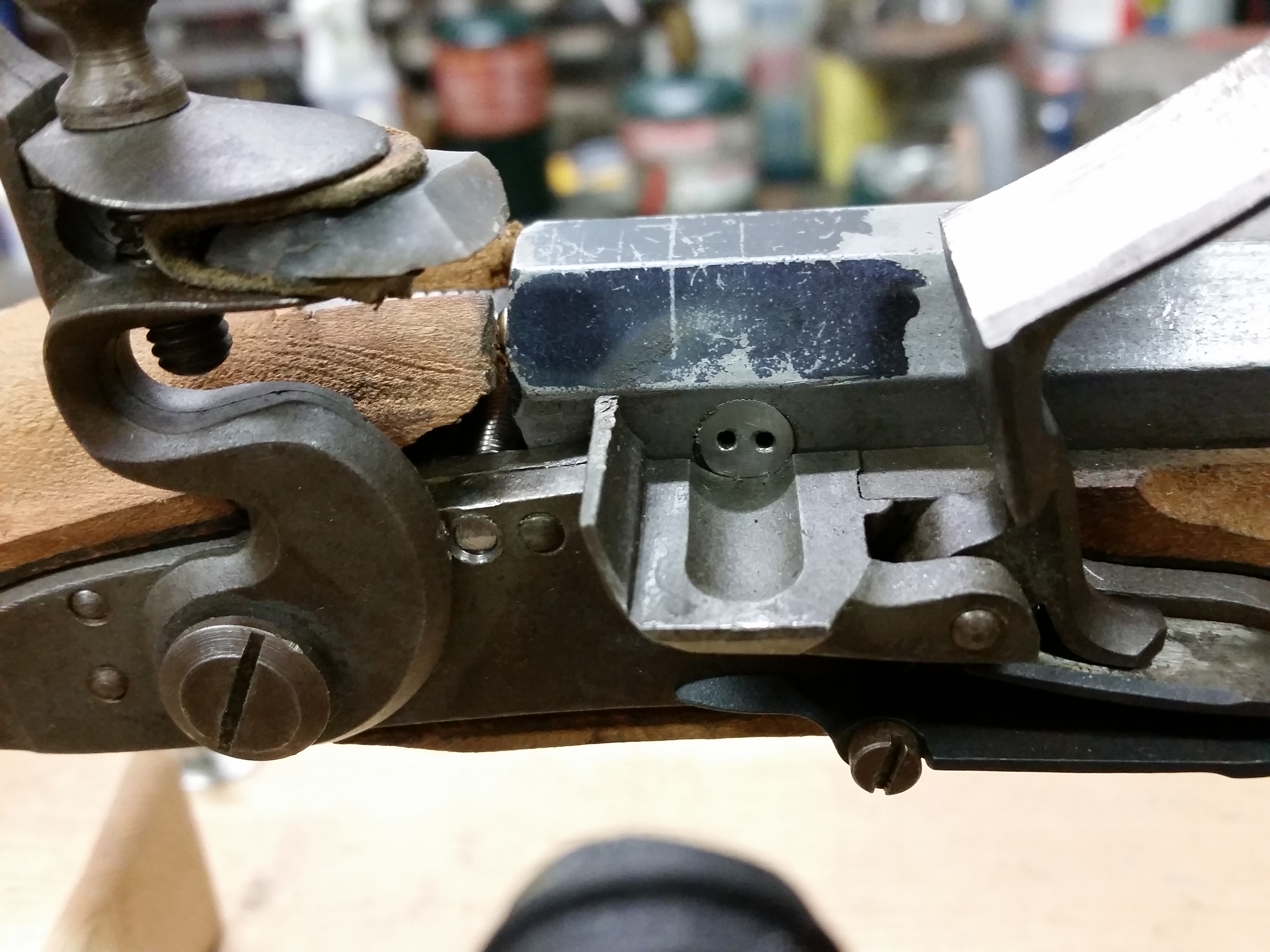
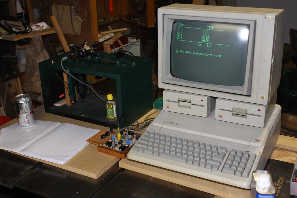
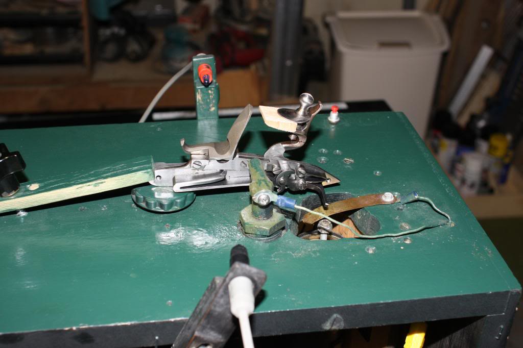
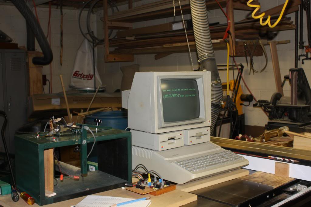
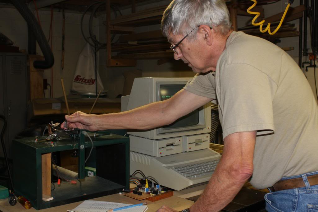
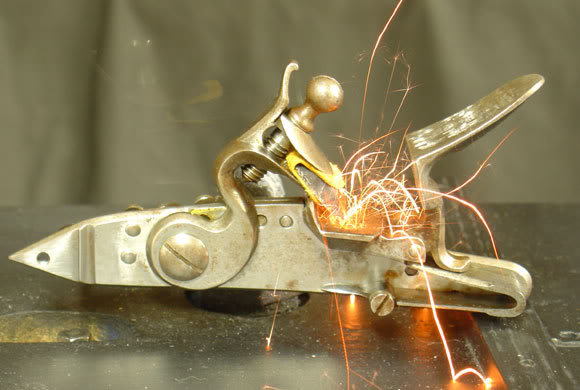
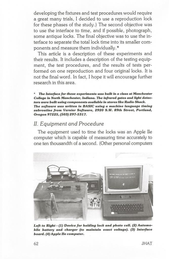
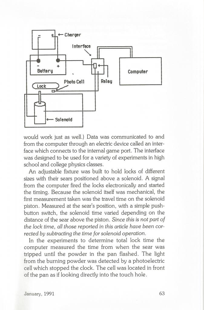
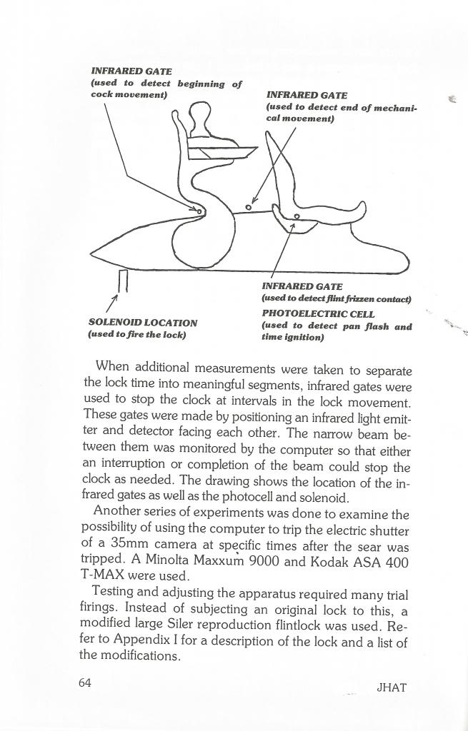
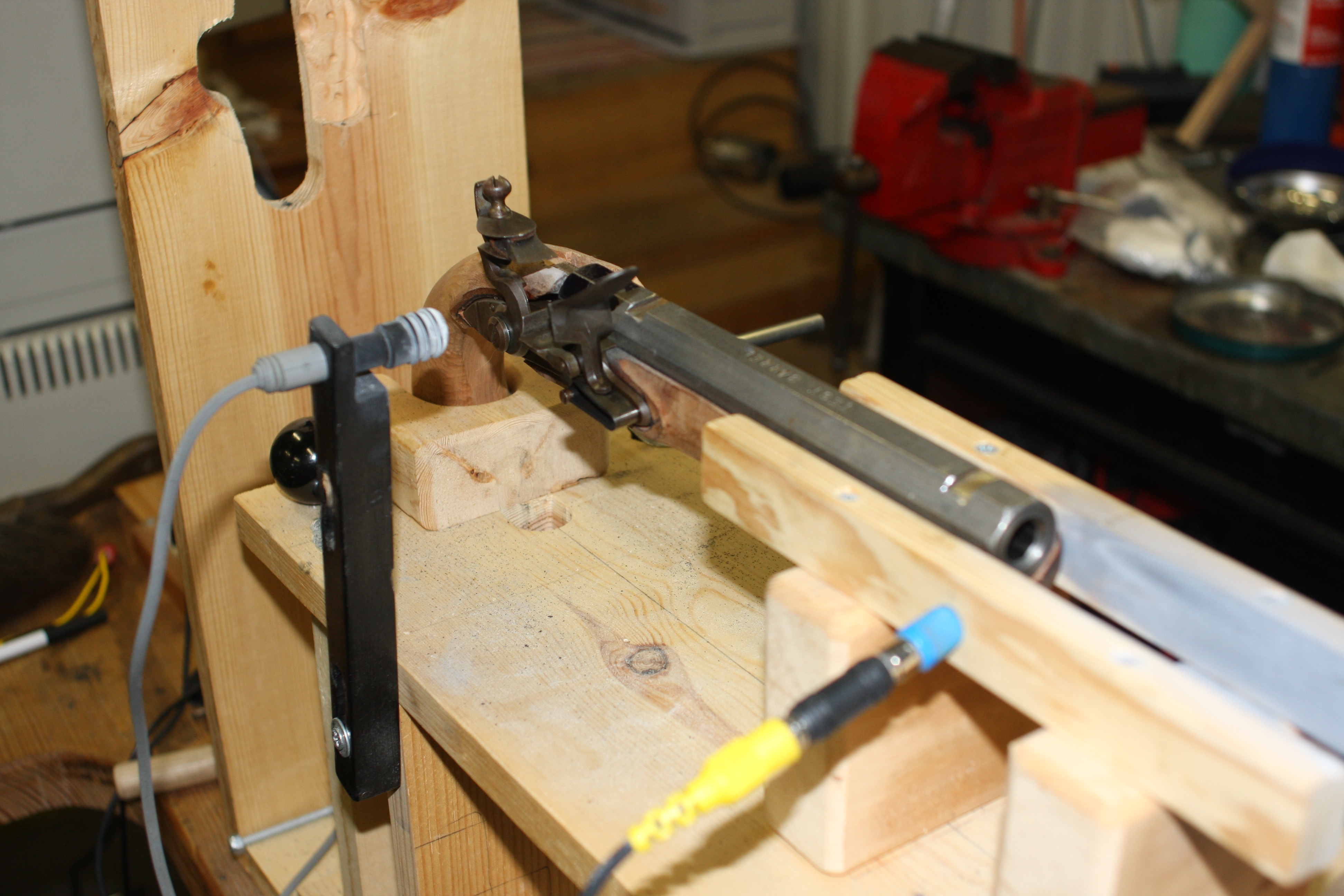
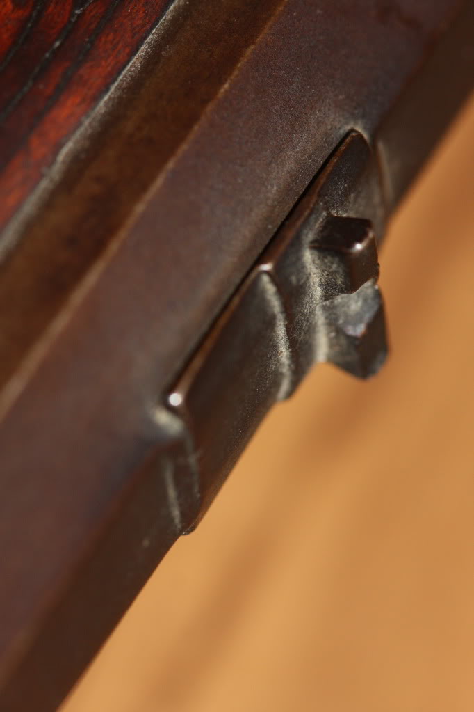
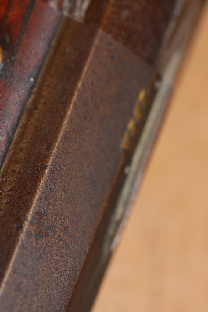
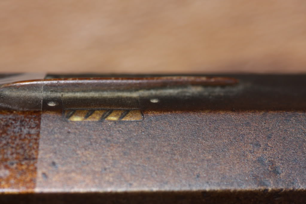
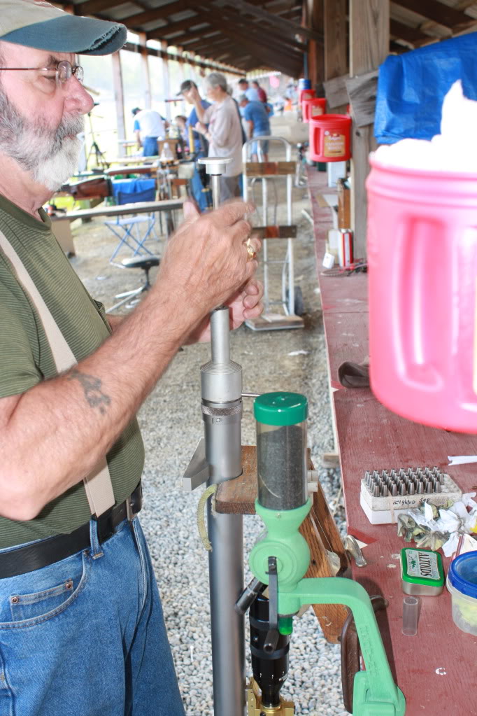
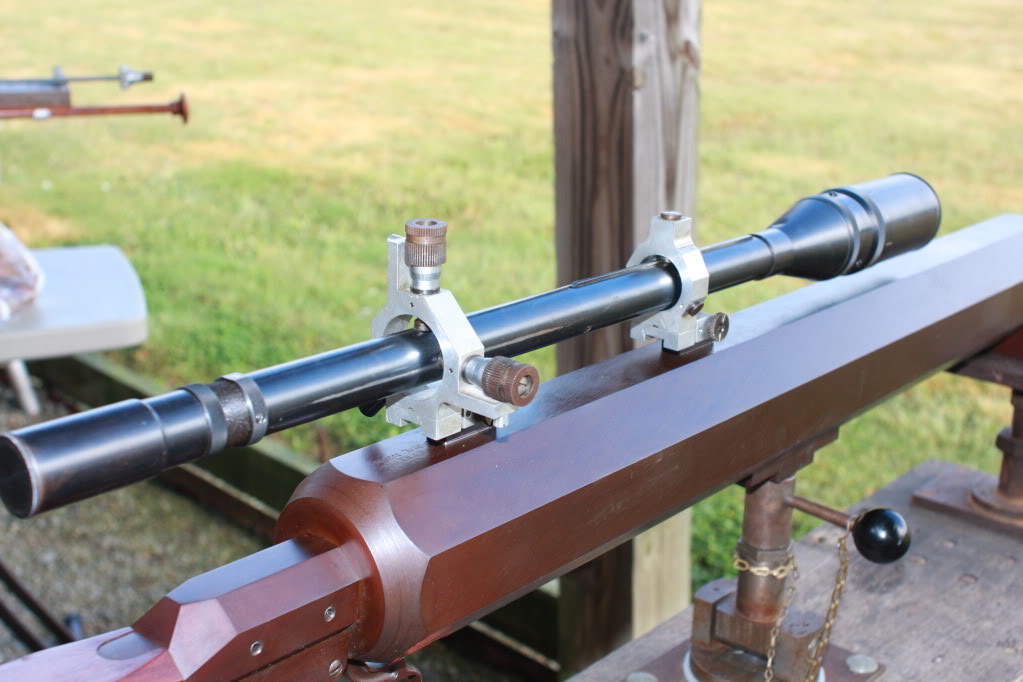
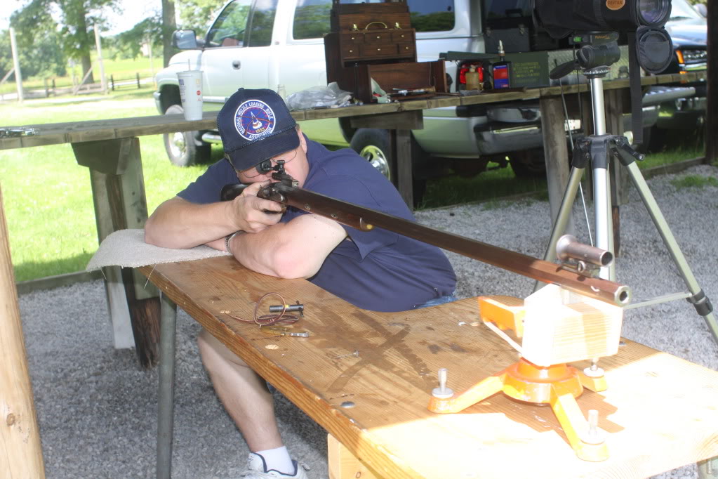
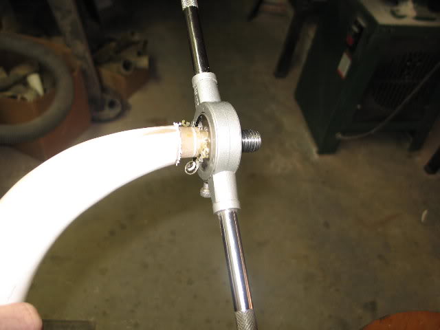
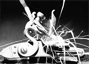
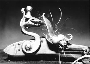
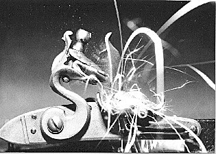
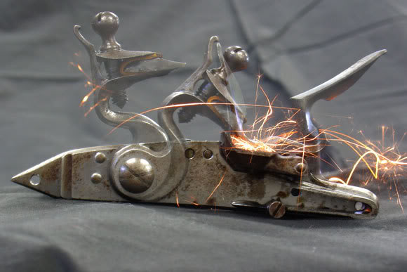
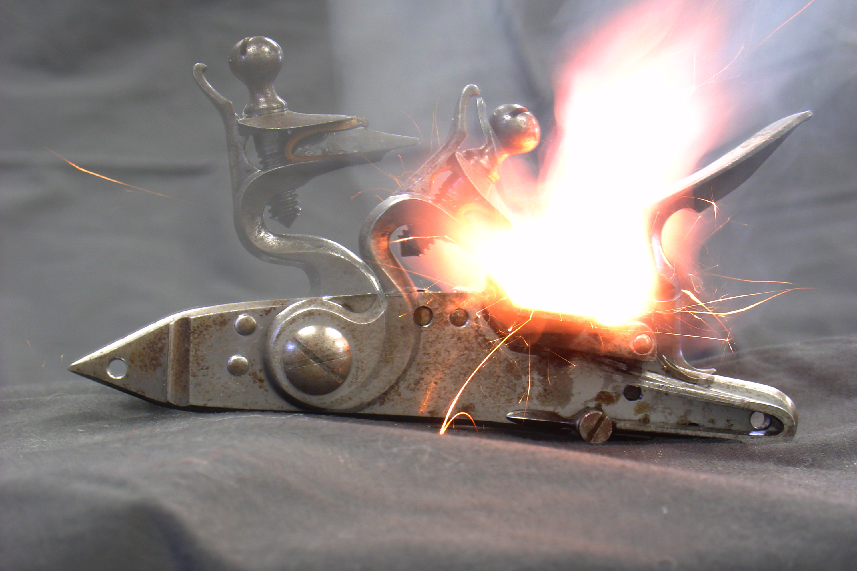
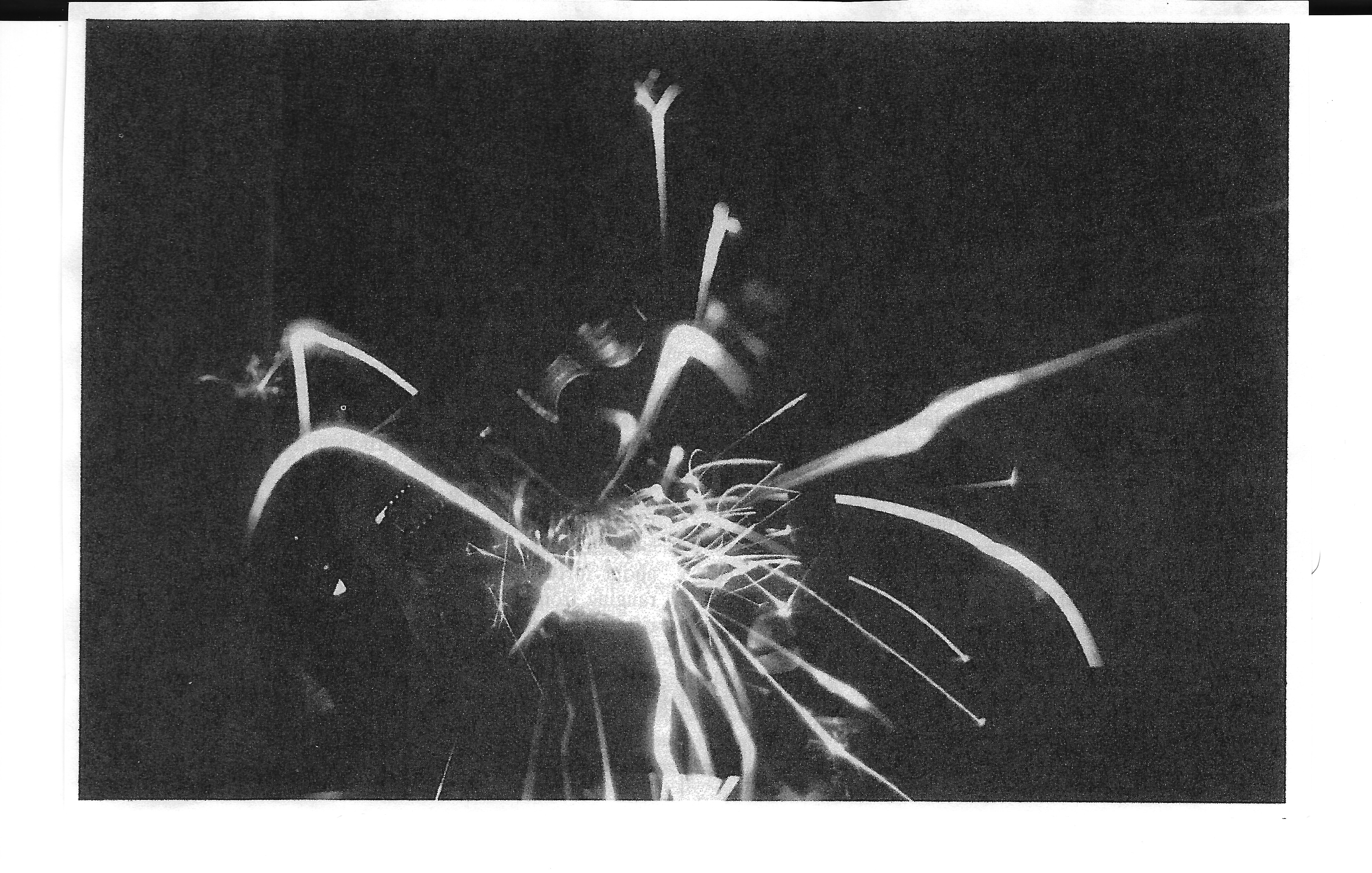
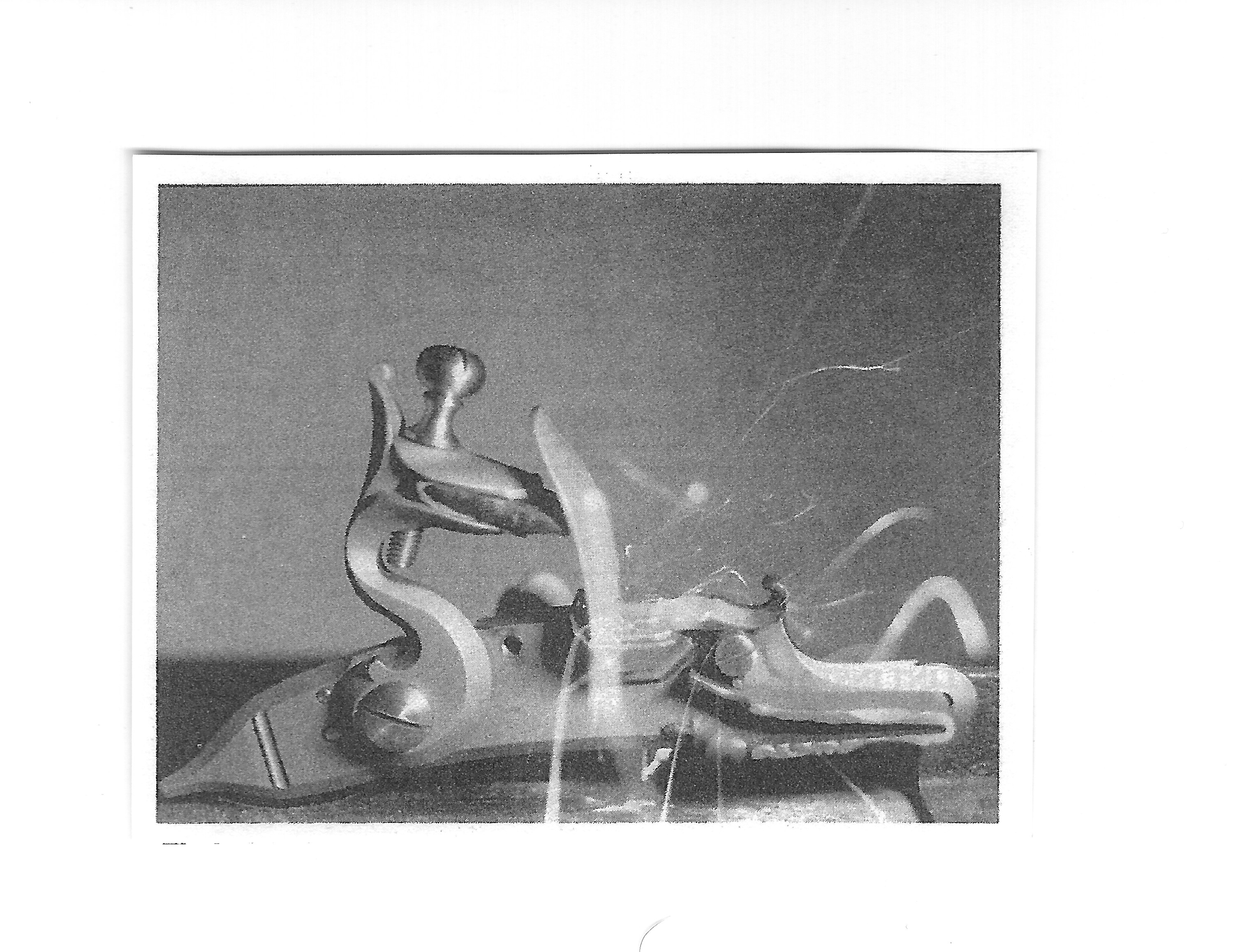
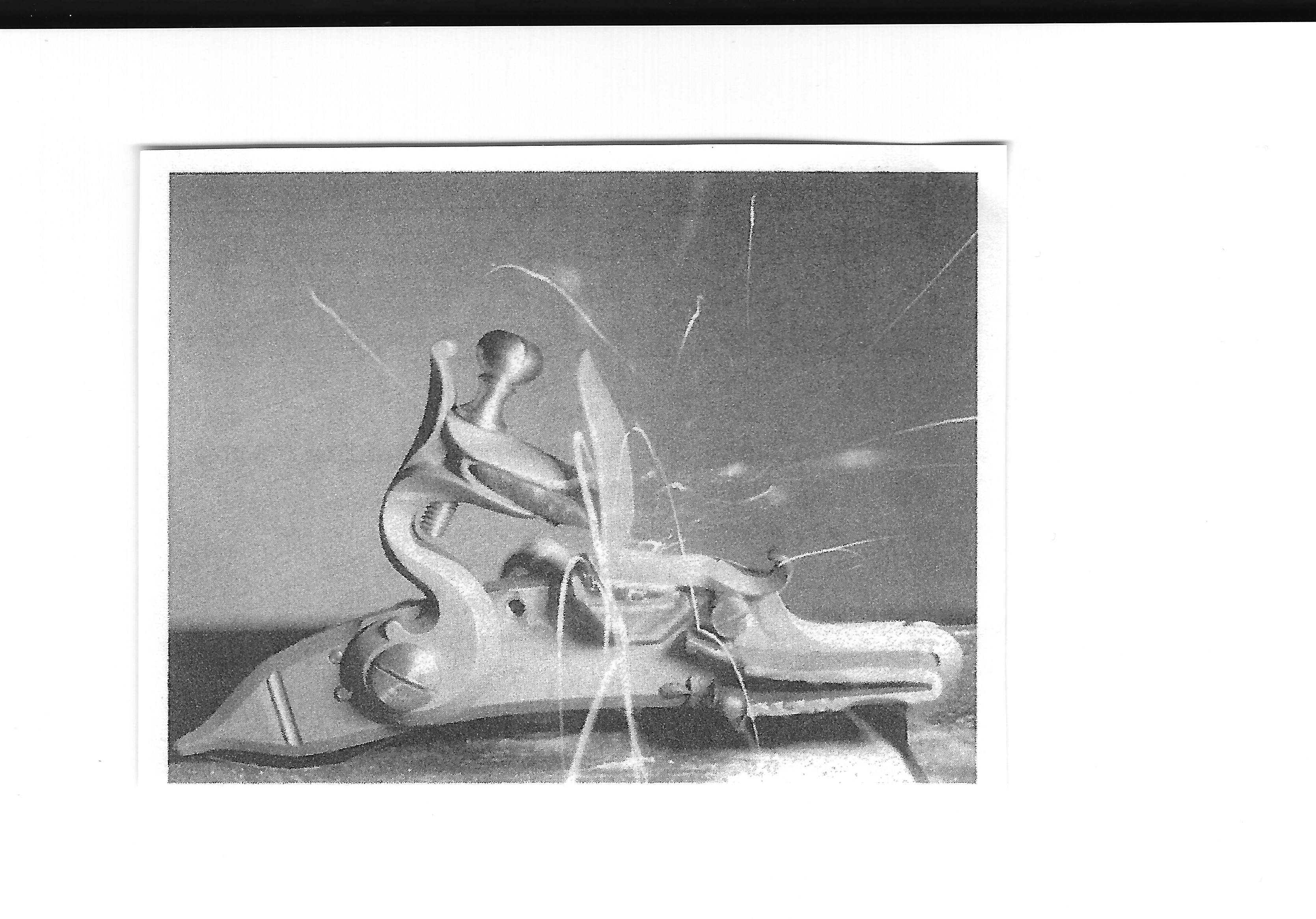
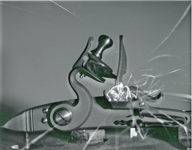
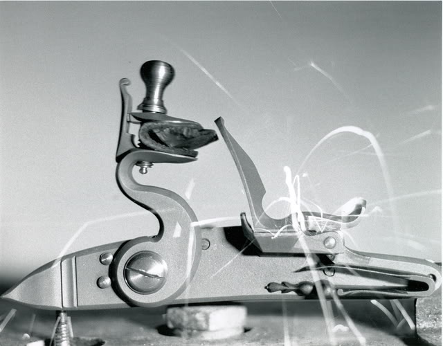
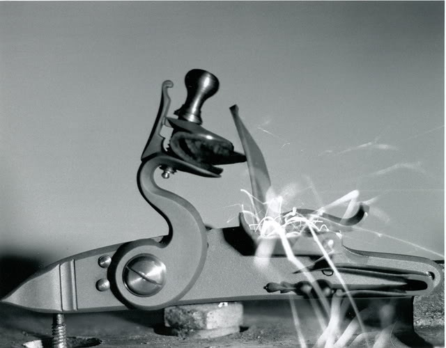
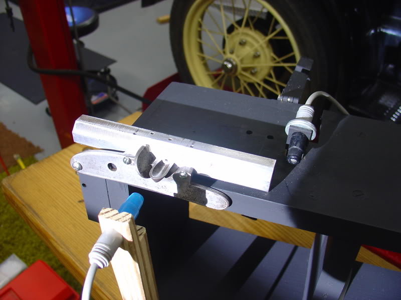
The barrel was held in place with a lock plate and pan attached to the barrel with screws. One photo cell was placed to “look” into the pan while the second “looked” across the muzzle of the barrel. A shield was dropped into place between them to keep the barrel photo cell from triggering on the pan flash. Both photo cells were connected to a computer by an interface.
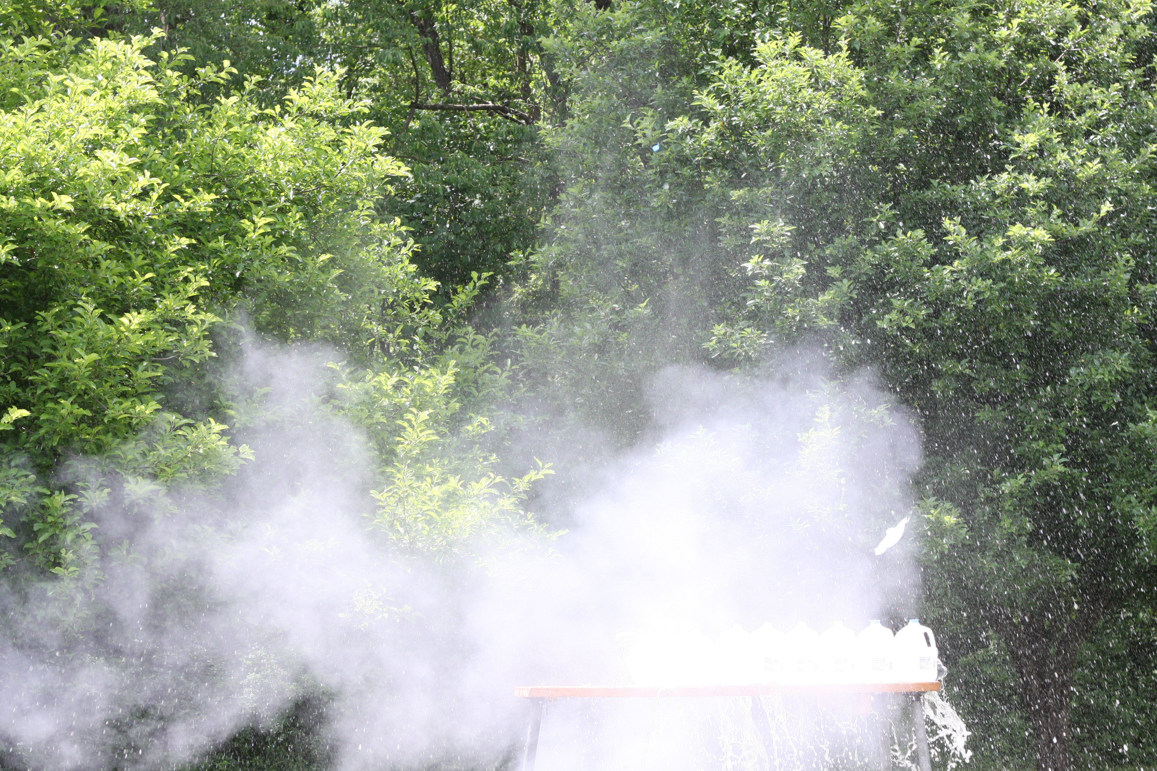
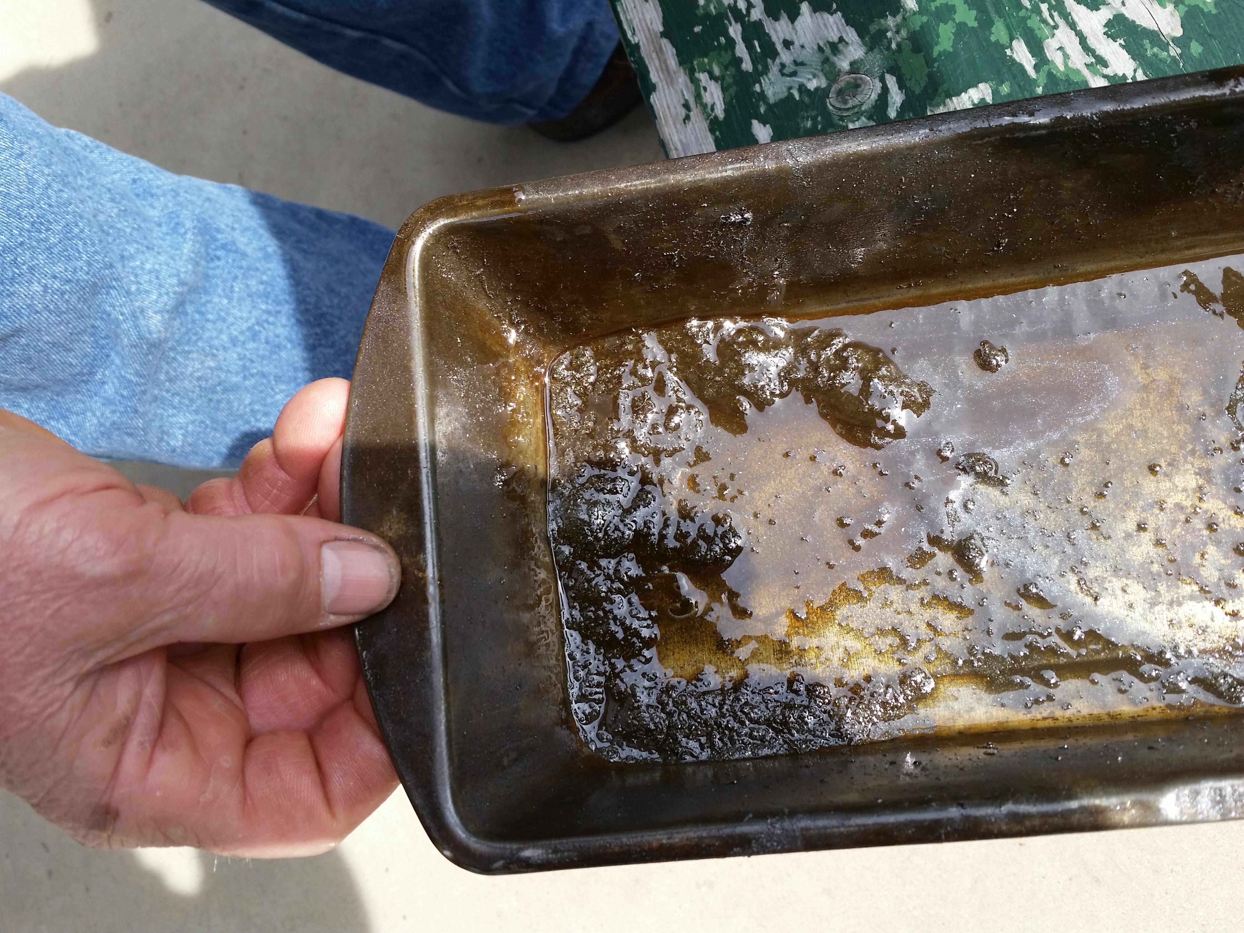
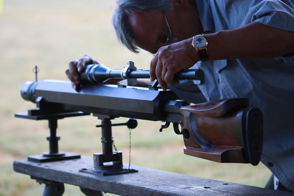
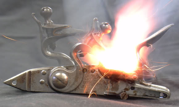
The testing process involved loading the barrel with 15 grains of FFFG powder. This amount of powder filled the barrel to a level above the touch hole. This was verified using a cleanout hole on the other side of the barrel opposite the touch hole. The barrel was gently lowered into horizontal position so the powder in the barrel would not fall away from the touch hole. The pan was primed, taking care not to cover the touch hole. The pan was ignited using a propane torch. It was found that the propane torch would not trigger the photo cells and could be directed downward into the pan. Special care was used to separate the torch from the powder used in the tests.
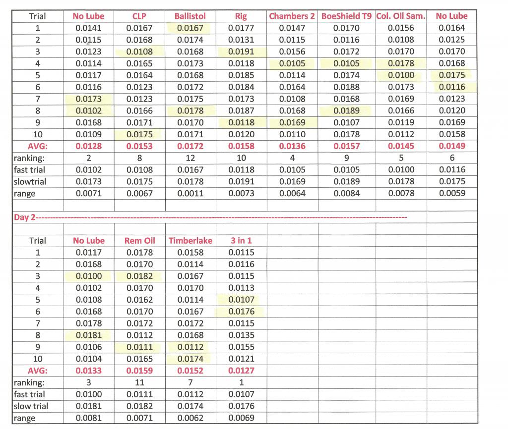
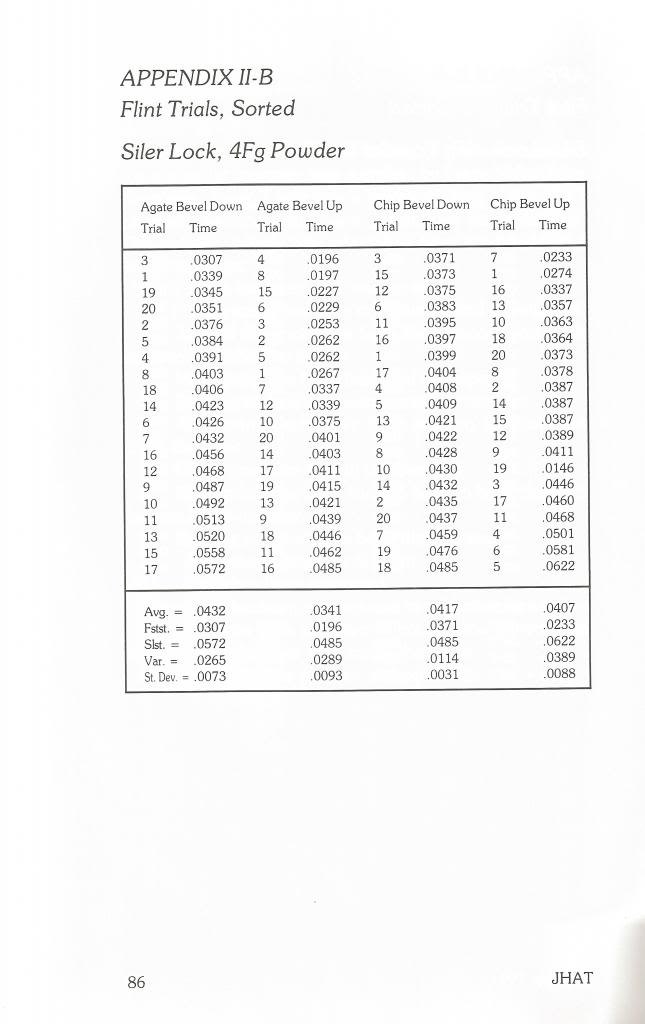
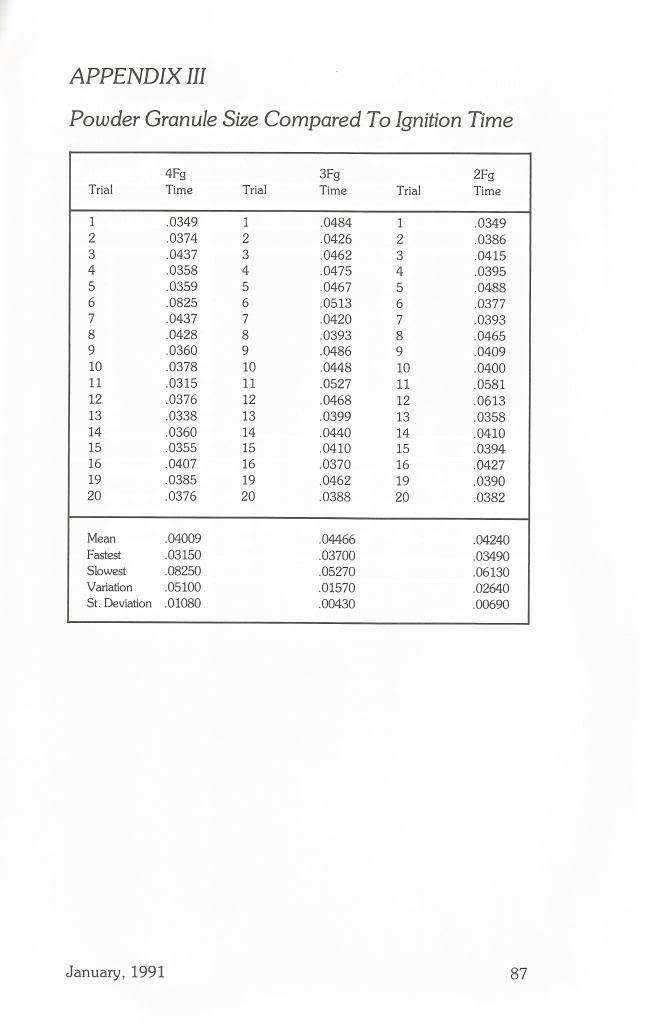
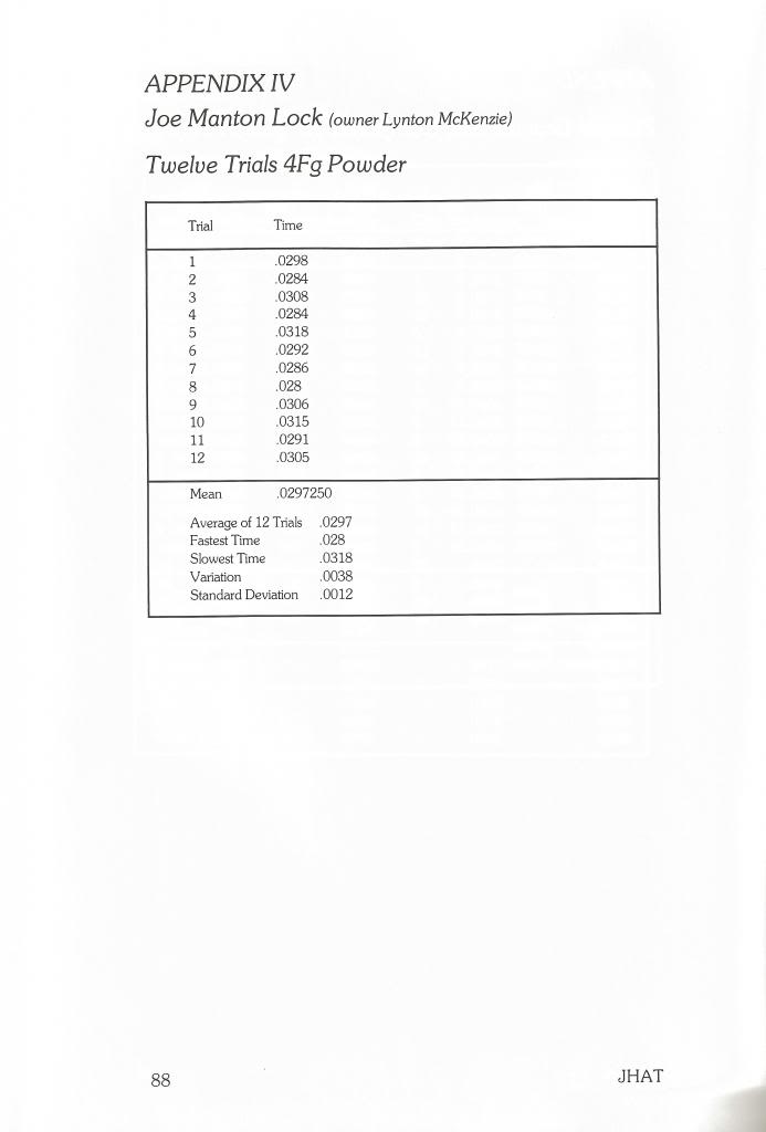
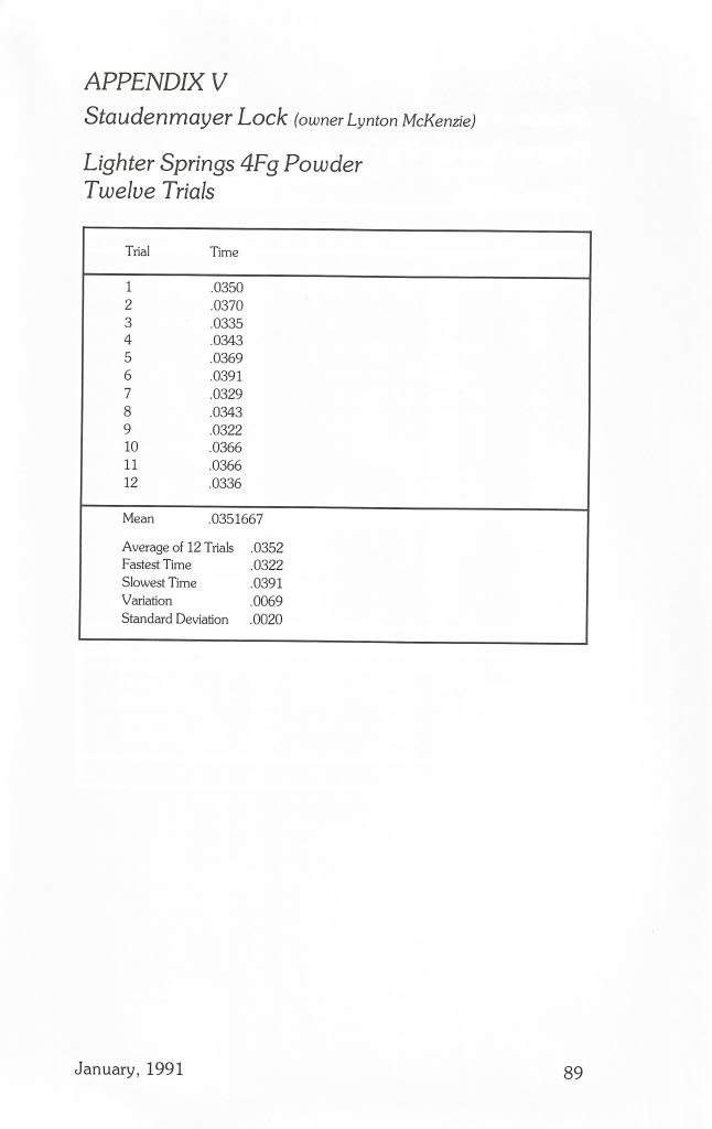
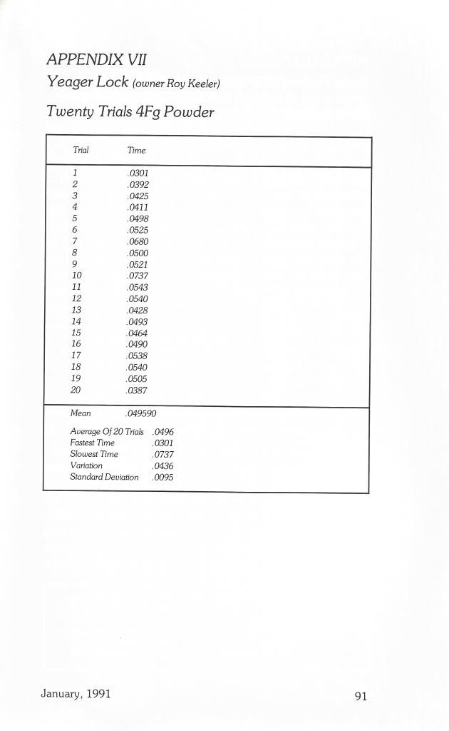
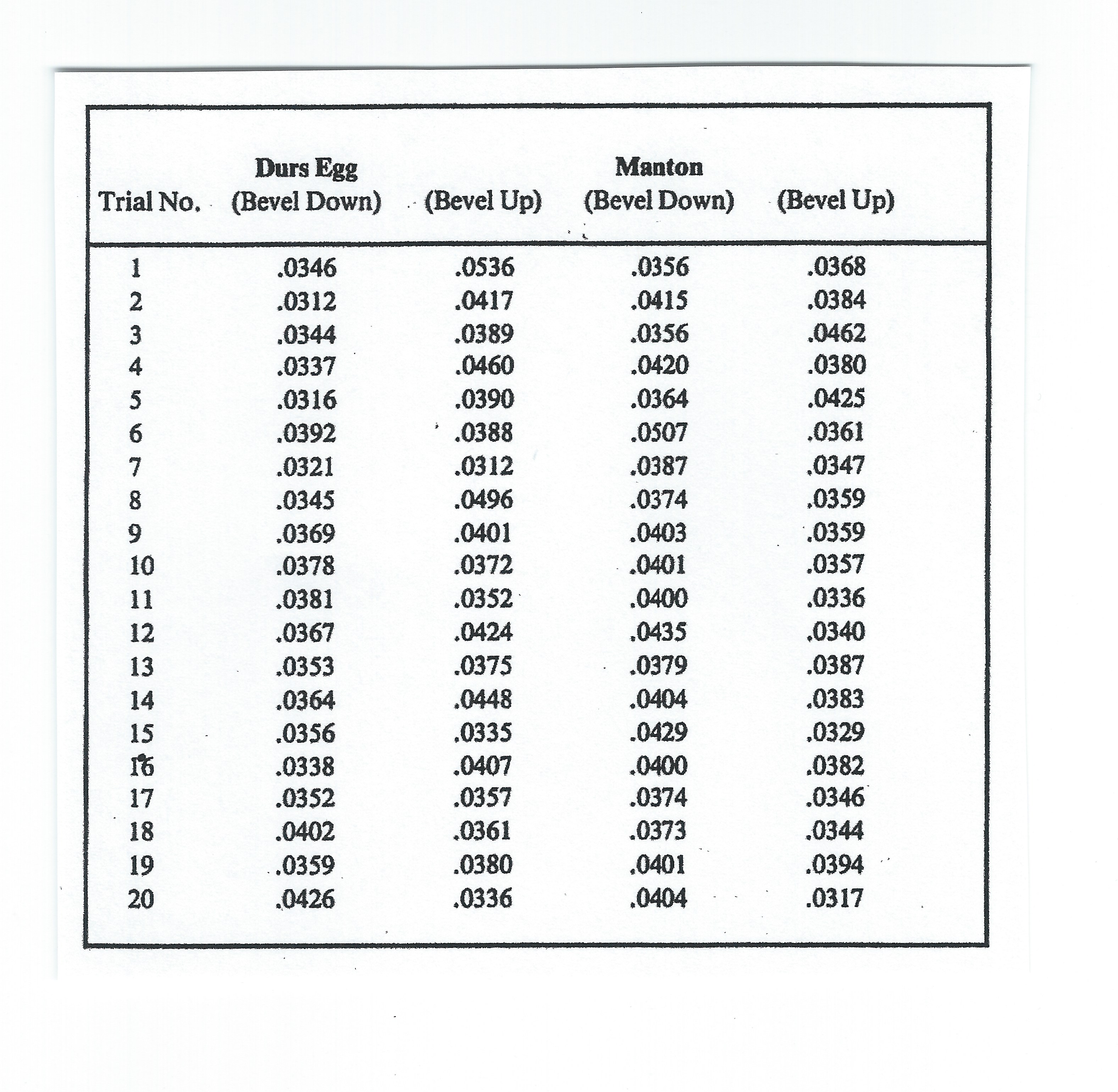
The .040 hole was tested only twice because I felt that it was too small to be practical. Each other hole size was tested 20 times. These tests are located in the spread sheets at the end of the article. After each touchhole was tested, it was drilled out to the next size and testing was continued.
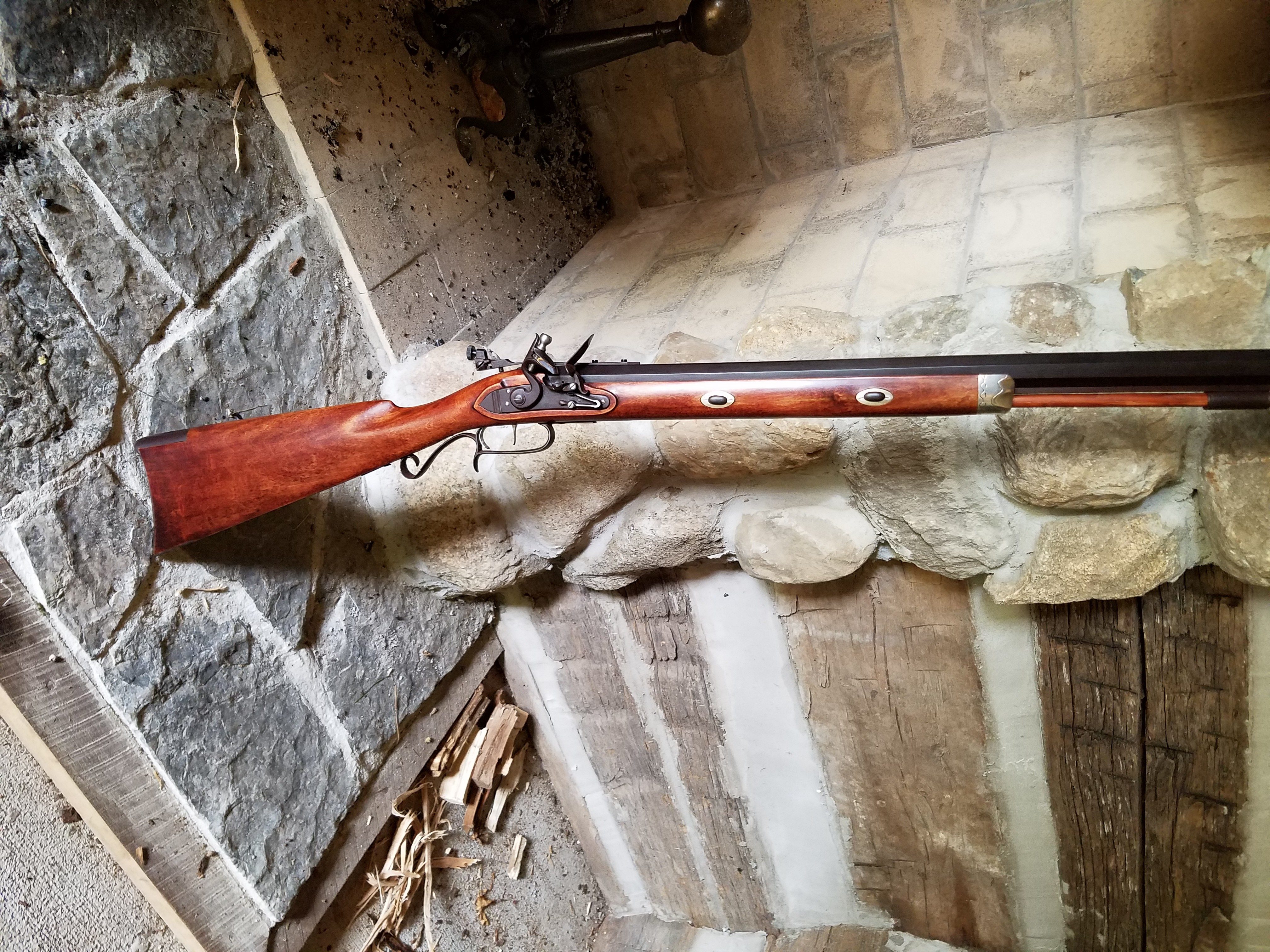
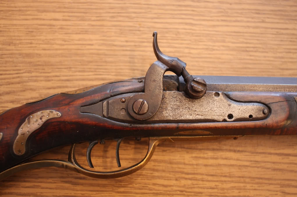
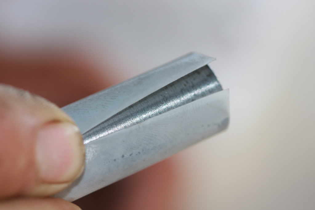
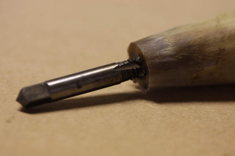
When I got to 1/16 inch, I permitted myself the experimenter’s prerogative of throwing in an extra variable. I have an exterior coned 1/16 inch touch hole in my rifle, so I used a center drill to produce a similar cone on the test barrel. Its results are also included.
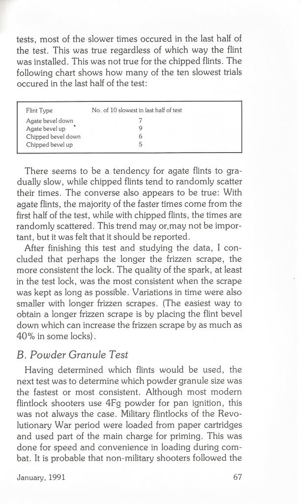
During the testing, a number of trends began to develop. It was noticed that with the small touch holes, a number of pan flashes did not ignite the barrel. This decreased as the diameters increased. When .055 in. was reached, this largely disappeared. Touch holes 1/16” and larger had no misfires.
A second result was that the ignition was faster as the hole size increased. The increase was dramatic in the smaller sizes. However, a point of diminishing returns was reached, in my opinion, somewhere above 1/16 in. At some point the improved performance that a larger touch hole seemed to provide was over ridden by the disadvantages of increased vent hole blast and decreases in consistency.
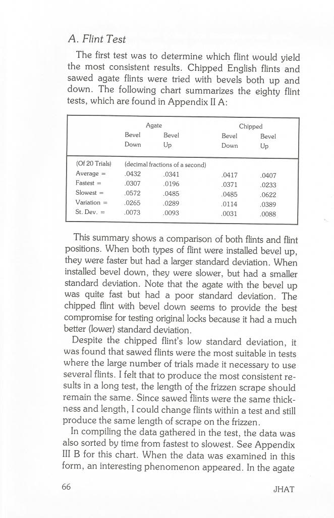
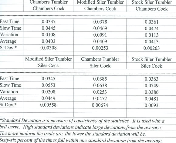
The standard deviation and variation within the tests can be used to demonstrate these trends in performance. Both standard deviation and variation improve as the touch hole size increased to 1/16 in. Above 1/16 inch, elapsed time, standard deviation, and variation are all more erratic.
As I mentioned earlier, the amount of gases escaping from the touch hole increased rapidly. It the larger diameters it was difficult to keep the torch from blowing out. While this was expected, it did serve as a reminder that large touch holes require that the shooter be considerate of the person standing to the lock side of the rifle.
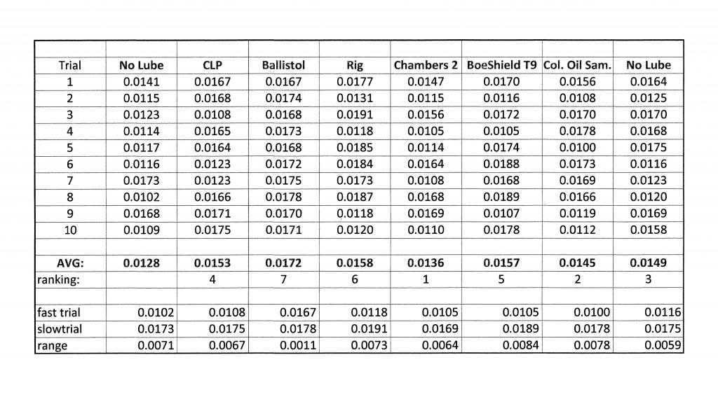
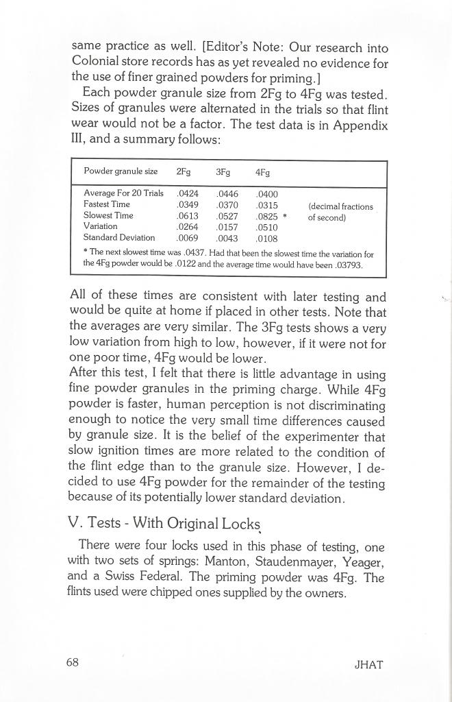
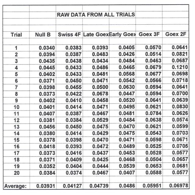
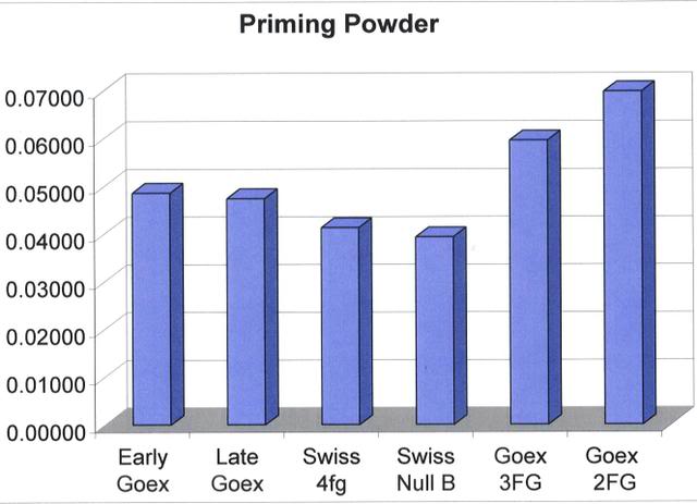
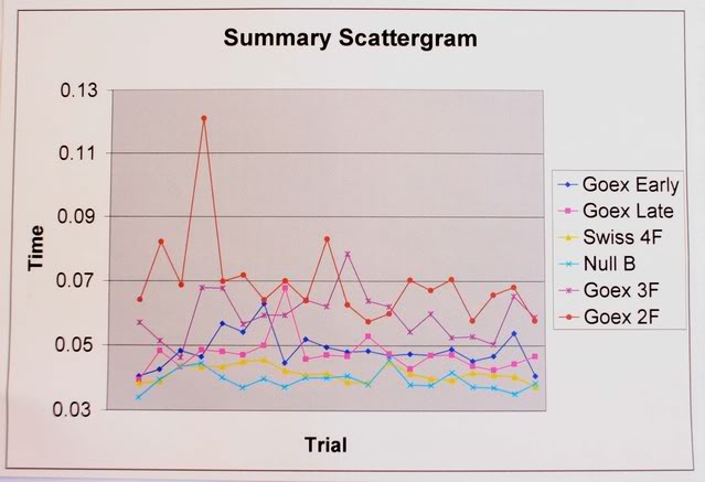
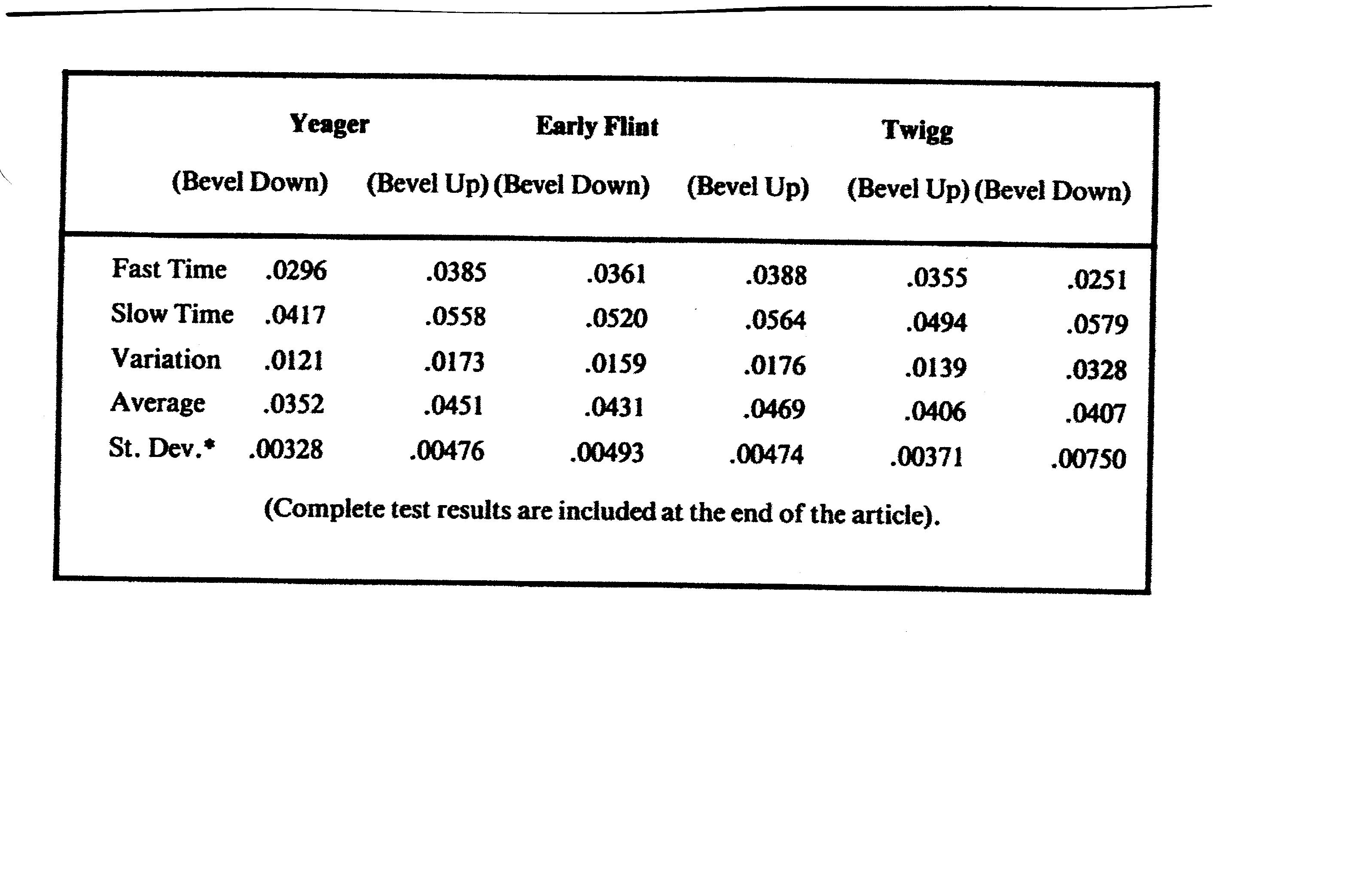
The results of the testing are summarized in the chart below. Complete results of each test are included at the end of this article on the next page.
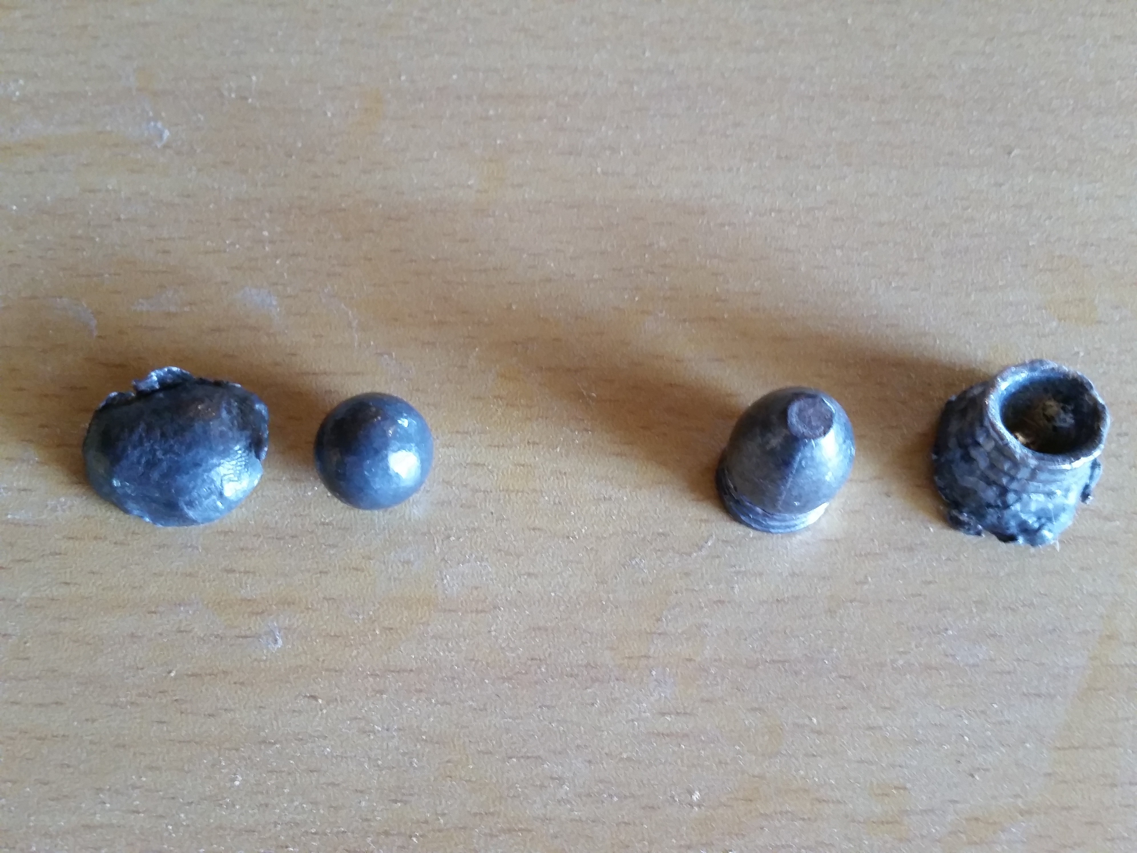
While cleaning the barrel between tests, I learned something that may be important in firing flintlocks. Looking through the inspection port opposite the touch hole, I saw that the touch hole was partially clogged. A vent pick was pushed into the touch hole while watching from the inspection port. I could see the dirt being dislodged as the vent pick went through. However, as the pick was withdrawn, the dirt was deposited back in the touch hole where it was at the beginning. This was seen more than once. It made me think that running the pick through the touch hole might not do as much good as I once thought.
It might be important to have a big enough touch hole so that even when partially clogged, it still has enough opening to ignite the barrel powder. Another possible solution might be to use a pipe cleaner before loading for the next shot. (In all my flintlock rifles I now use a vent large enough to permit cleaning with a pipe cleaner. – editor)
By the end of my testing, I arrived at two conclusions that will be incorporated in any future rifles I build. One conclusion is that if no liner is used, any touch hole will need to be 1/16 in. or larger in diameter. The other is that it will have an exterior cone. I believe that an exterior cone improved the 1/16 in. touch hole enough to be included. It would, however, be good to test an exterior cone on different touch hole diameters.
As was explained earlier, this article ignored touch hole liners. It was felt that a baseline was necessary for any future comparison. The next article will be devoted to liners. I personally like the idea of having barrel powder lie as close as possible to the pan. I am probably not alone in thinking that liners will show an improvement over cylinder touch holes. However, I am willing to rely on science to demonstrate this. Human senses are not perceptive enough to detect the differences we can measure with the computer.
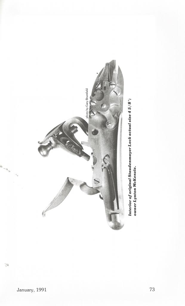
There are numerous liners and methods of installation that should be examined. I would like to try a sampling of those currently marketed. A liner that seems to function well has been developed by Mark Silver, Robert Harn, and Jim Chambers. It is based upon information from Lynton McKenzie. It will be interesting to compare these liners with the results of this series of tests. As in any scientific study, I hope we will be able to draw some meaningful conclusions.
I do not consider this to be a complete study of cylinder-shaped touch holes. We do have much to learn. However, I have confidence in the results collected and in the methods that Fred and I devised to do the study.
I am open to any suggestions that will further our understanding of flintlocks. Soon I hope to have a web site devoted to flintlocks. In the meantime, please feel free to write me at 4595 E. Woodland Acres, Syracuse, IN 46567 or email me (larry@blackpowdermag.com)
Summary Chart
Larry Pletcher, editor – www.blackpowdermag.com
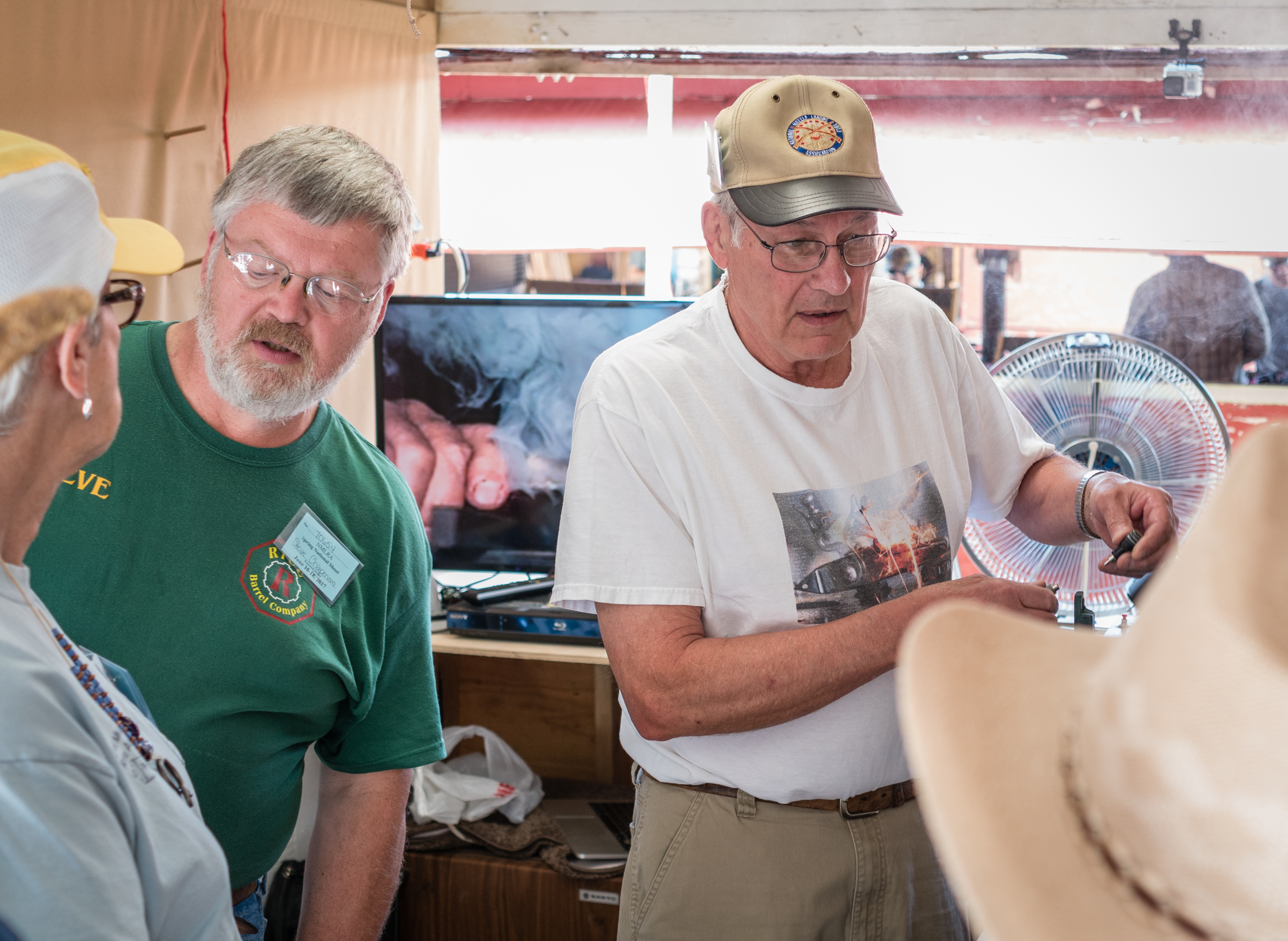
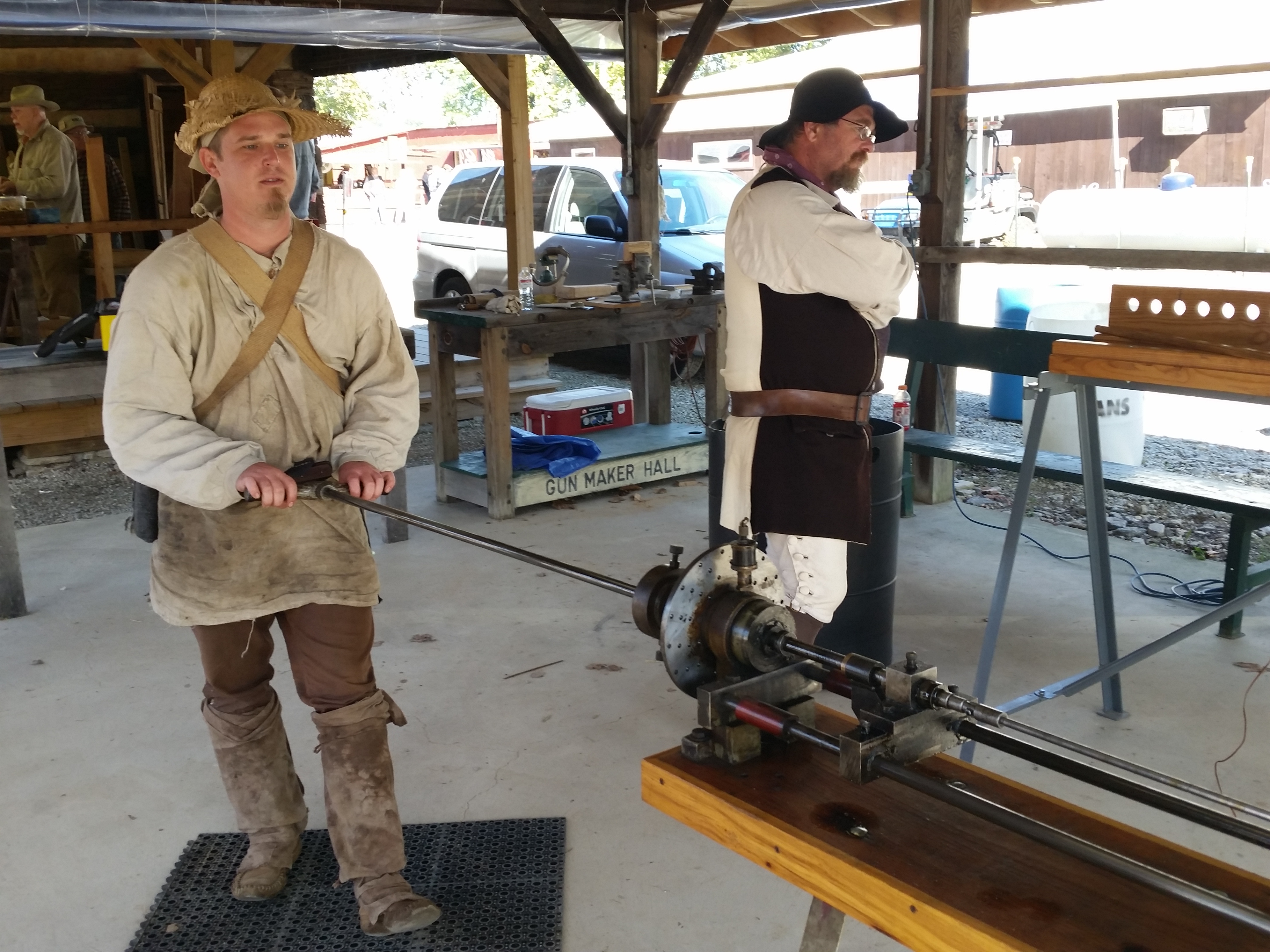
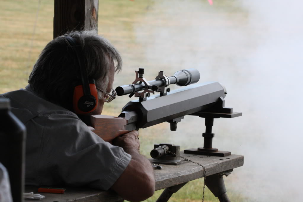
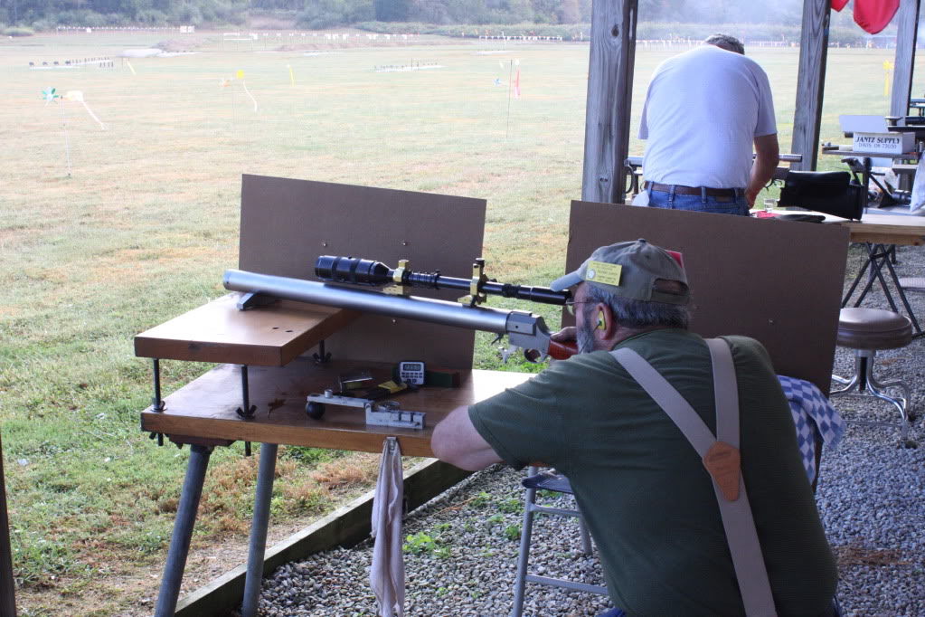
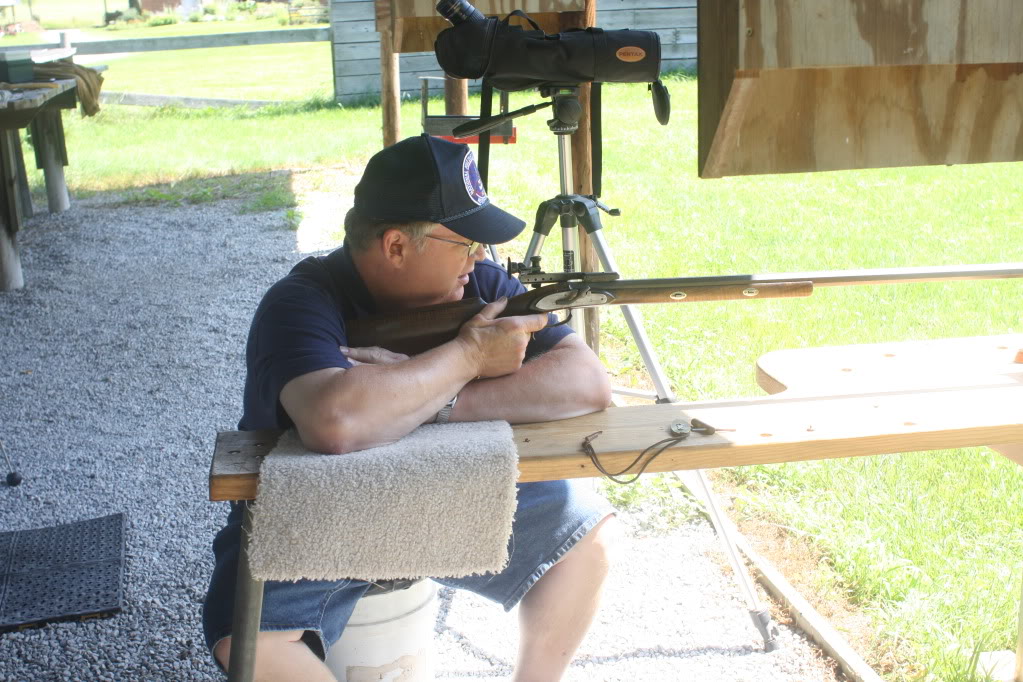
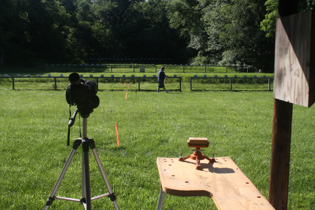
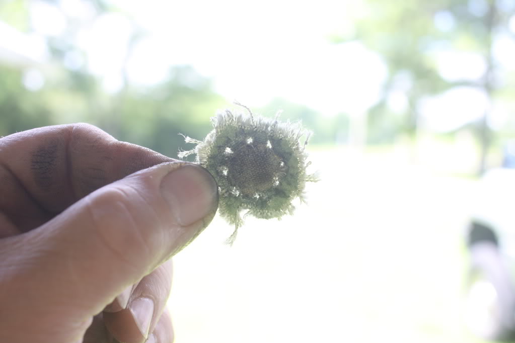
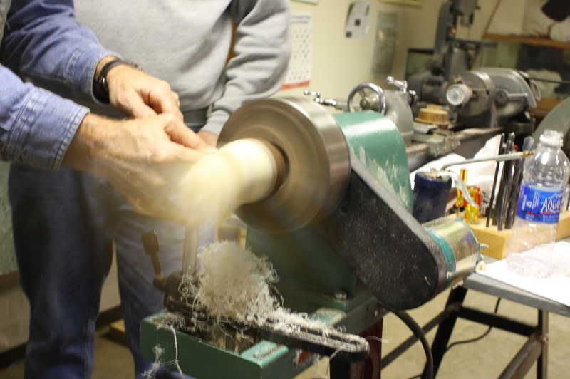
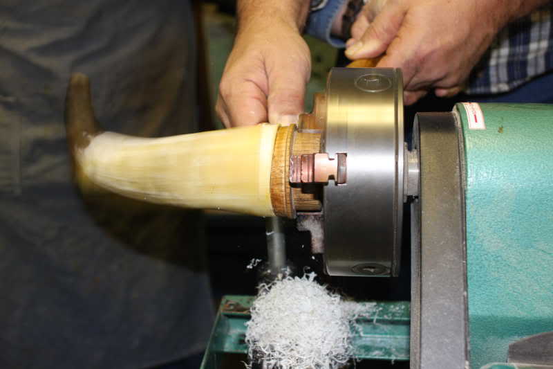
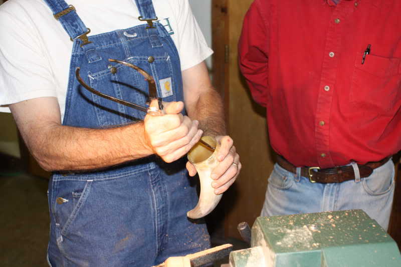
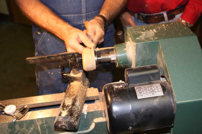
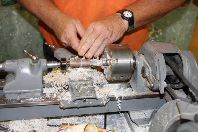
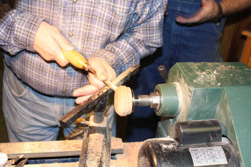
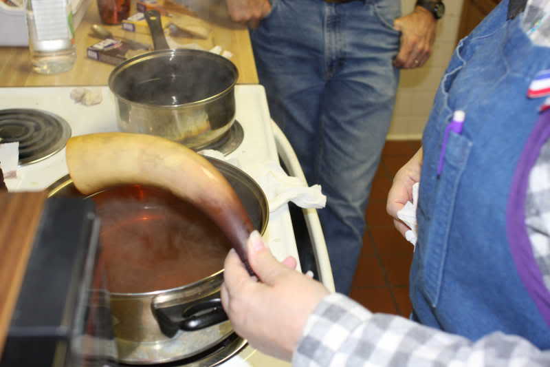
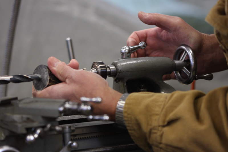
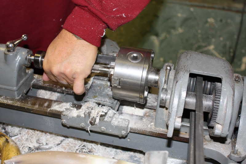
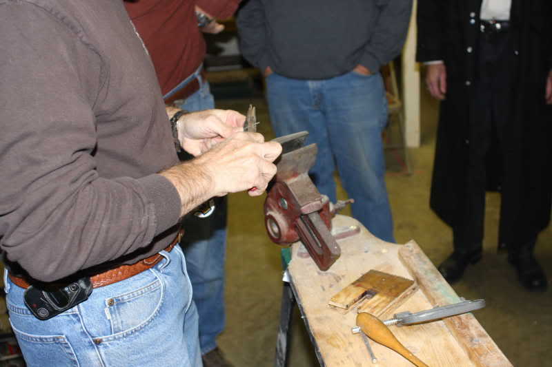
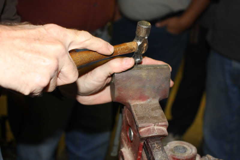
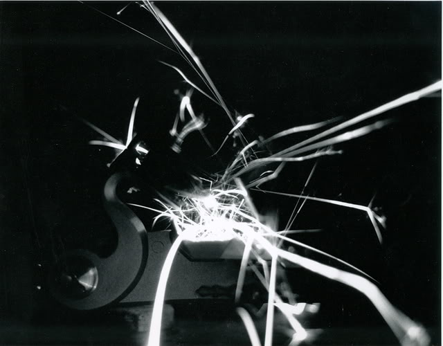
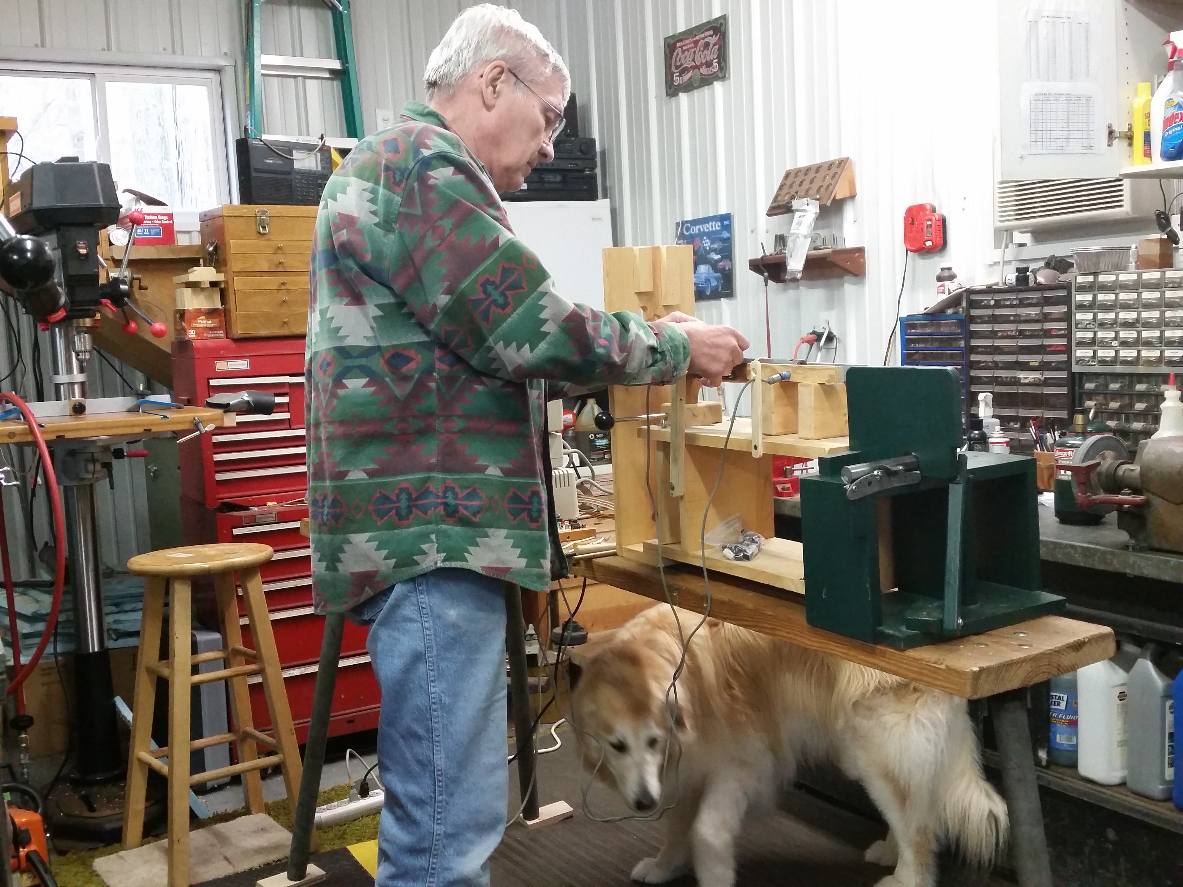
Because this article was published 19 years ago, I am having trouble locating the photos that were used in the magazine. I added photos of more recent testing that uses the same equipment and methodology. My summary chart is also missing. It appears above, cut and pasted to fit the page. The spreadsheets below are original to the magazine article.